If I ever upgrade my power I would likely buy this supply. I would have recommended it earlier but could not find it. The one downside is that I have not opened one up and captured the internal circuitry so we don’t know what is in it.
I never really understood the function of the Ethernet port on this supply but I suspect it could be a serial control port perhaps for manufacturing.
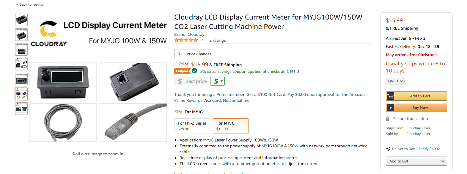
I think the status display is useful and it doesn’t seem to increase the cost.
I wondered whether it was modbus. They have other supplies with modbus but I didn’t see any mention of it in the product listing… There is a more expensive supply with modbus and remote display, too.
It looked to me like the display added $4 to the cost when I followed the bread crumbs back and clicked on many of the items on that page.
Found it again. It doesn’t say “modbus”. I don’t know what “special serial port” is. Maybe SPI? It doesn’t say whether it runs modbus or something else at the protocol level.
Now that I’ve ordered most of the mechanical parts, I look at the relatively small difference between an 80W Reci W2 tube and a 100W Reci W4 tube and realize that if I’m going to have a wart off the right side to hold control electronics, a smaller wart on the back side to hold a longer tube would not be crazy. 100 or 200mm would do the trick; it’s a 1400mm tube and tube and first mirror head assembly together have 1540mm so a tube wart is probably called for.
That power supply can supply 28KV (the W4 triggering voltage) and 100W, and I wouldn’t want to push the tube past its continuous rating anyway.
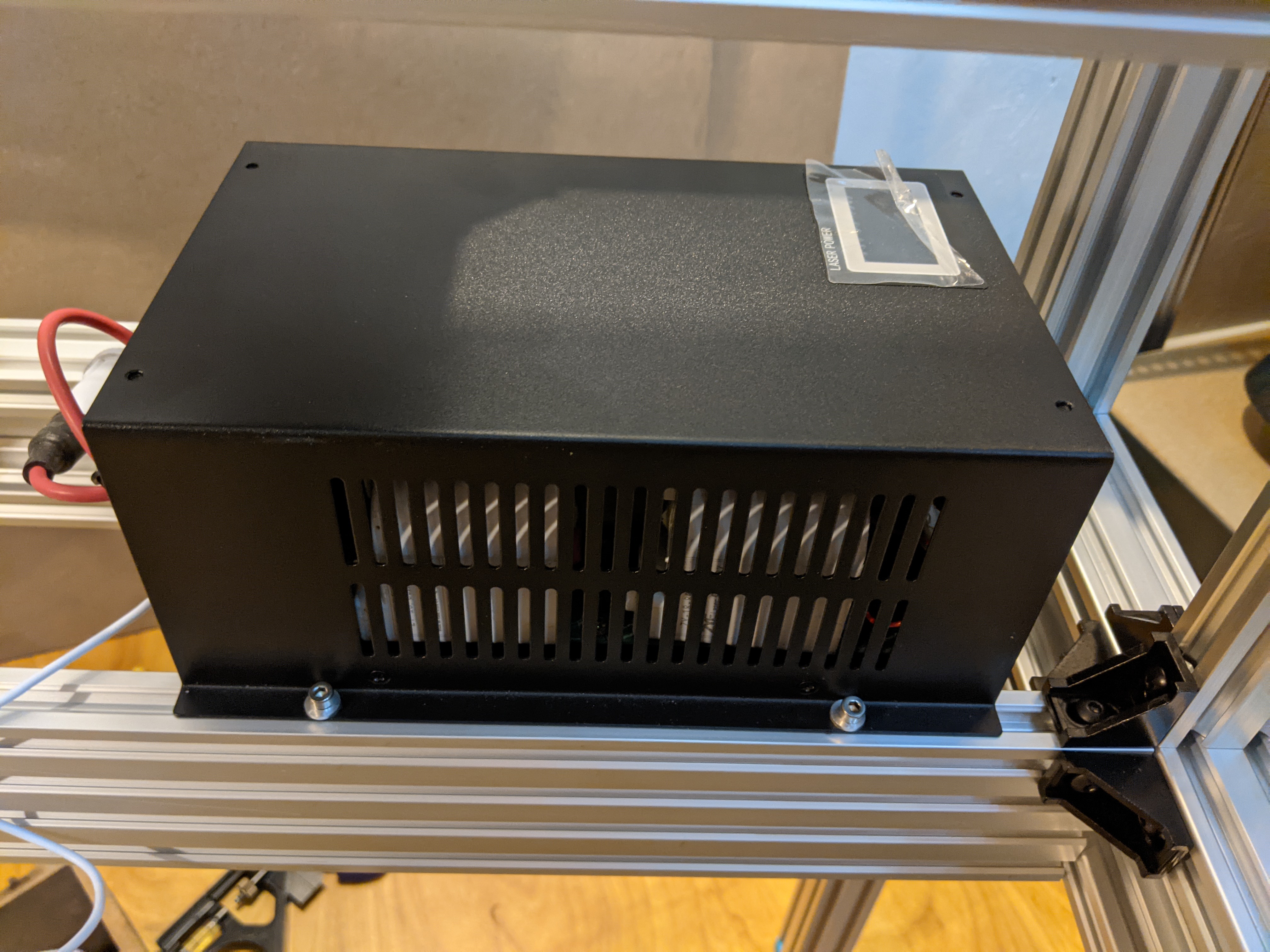
The MYJG-100W shipped with lots of HV wire and an HV coupling set. It’s probably too late to return the wire I bought from amazon early on. It was also very well packed.
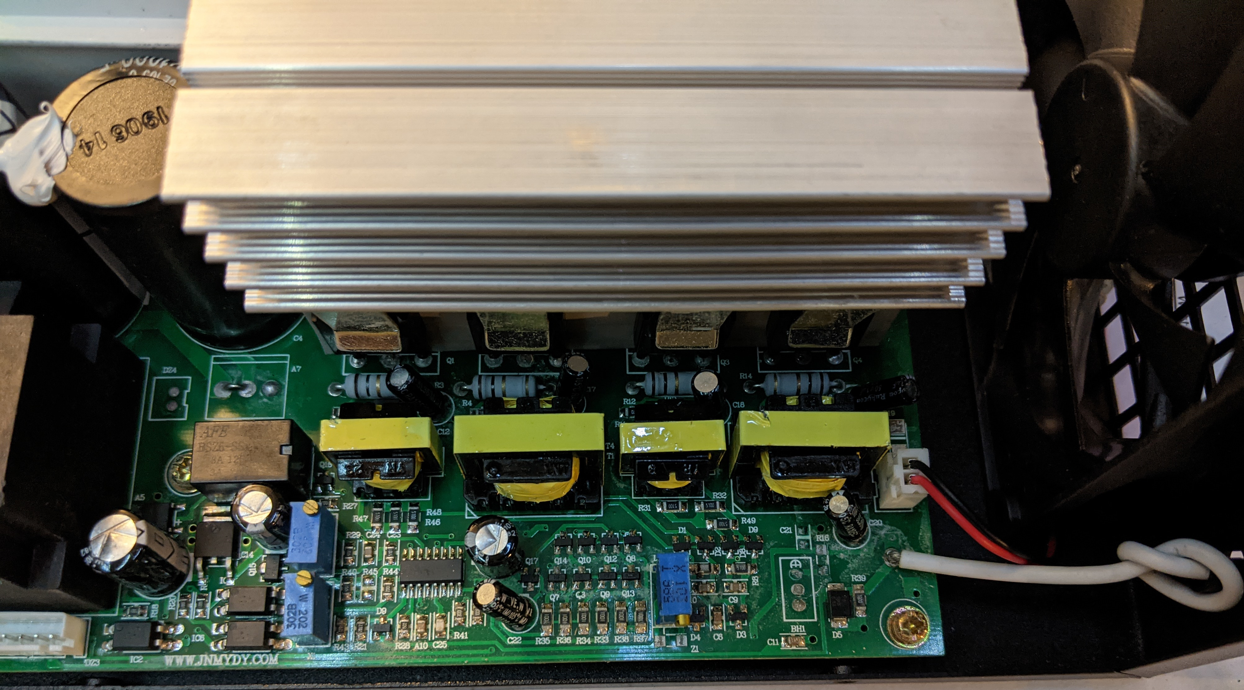
I didn’t trace out the schematic but I satisfied my curiosity in other respects regarding the insides.
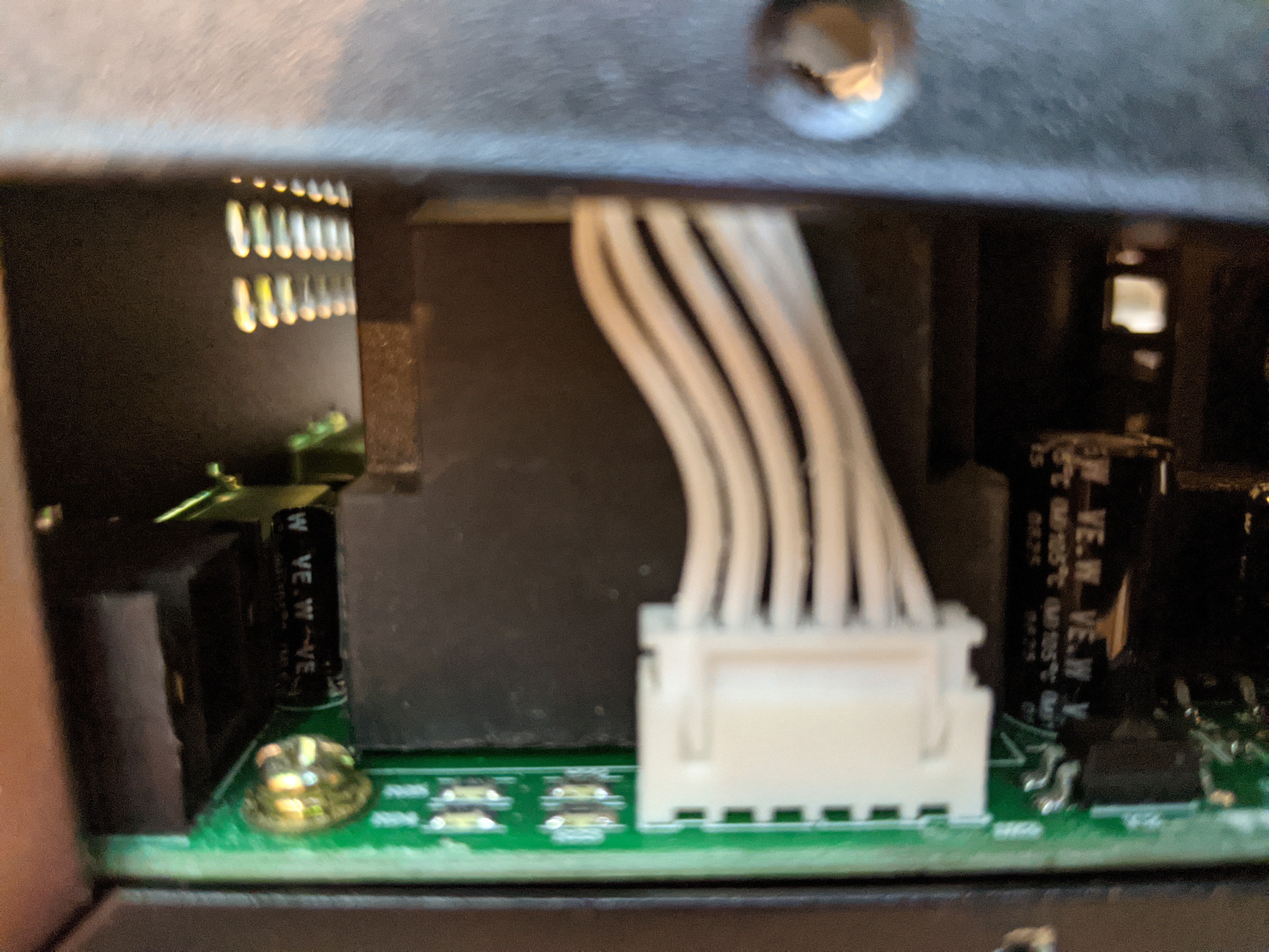
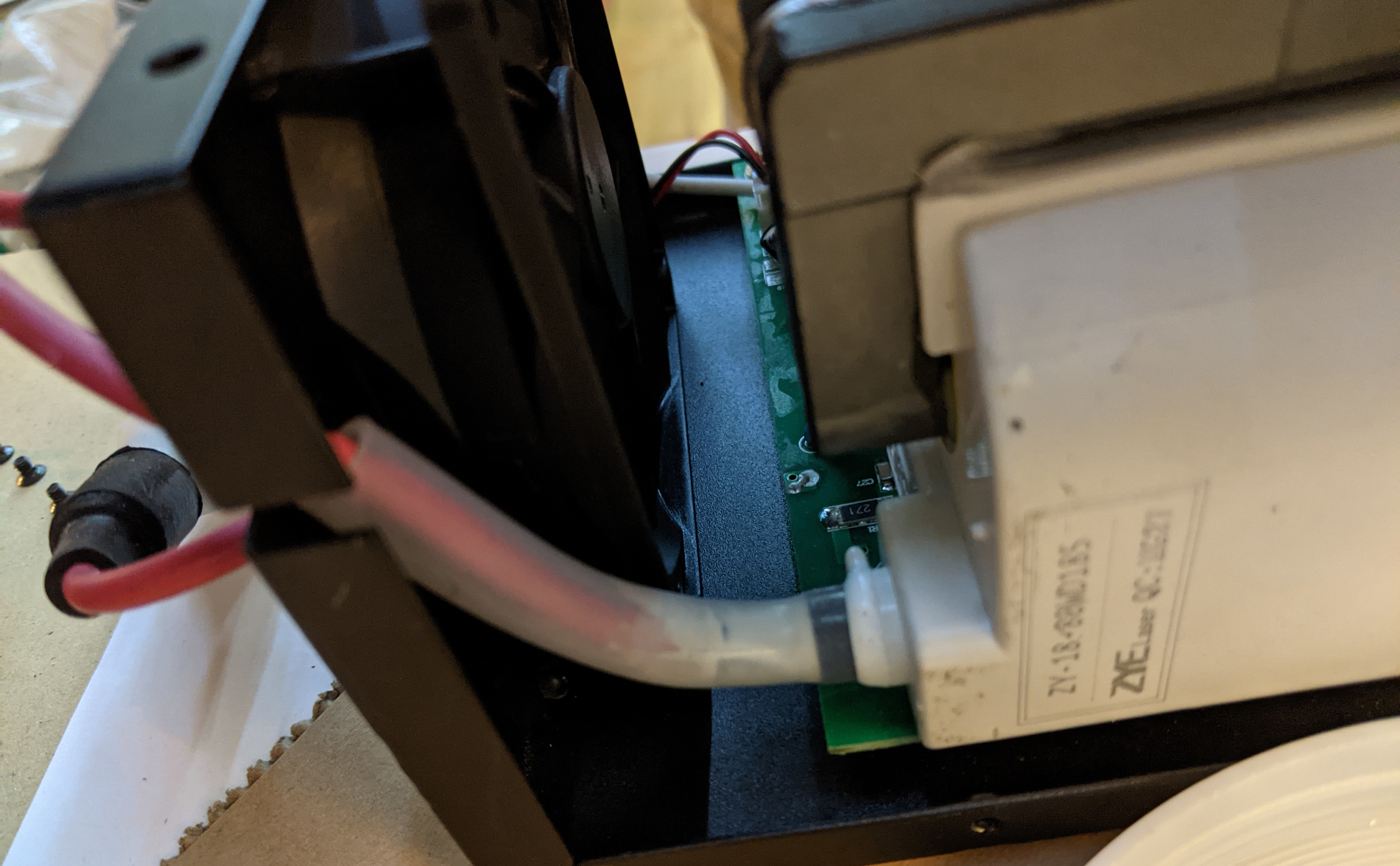
It comes apart easily with two small philips screws on each side, but the harness for the display is short and the harness needs to be disconnected from the board to remove the lid. Sorry I didn’t realize that this picture was blurry; I’m not planning to pull it apart again to get a better shot:
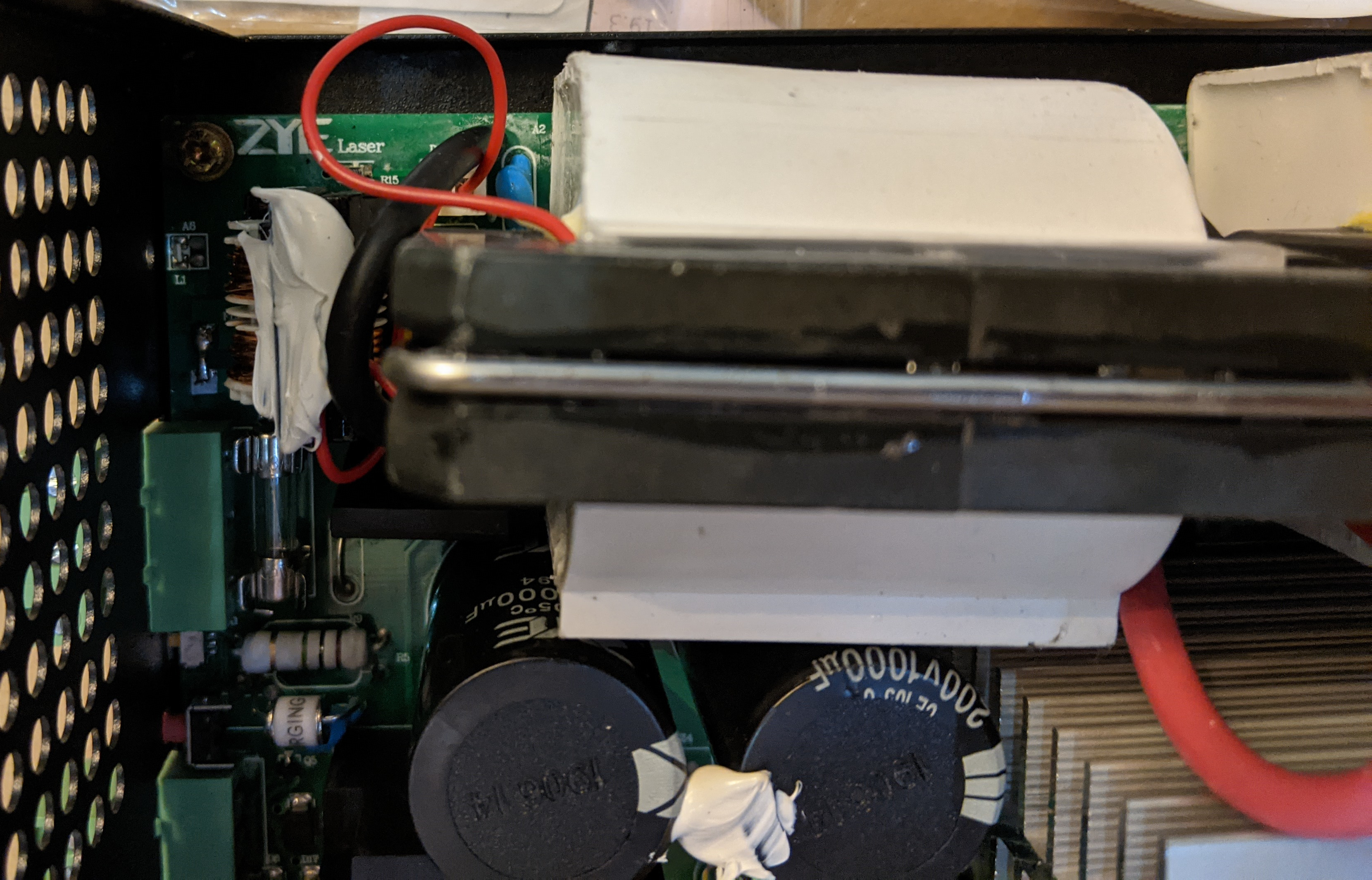
After removing the connector blocks, disconnecting the fan, and removing five more philips screws from the board, the board lifts out with only some gentle work moving the anode and cathode lines around.
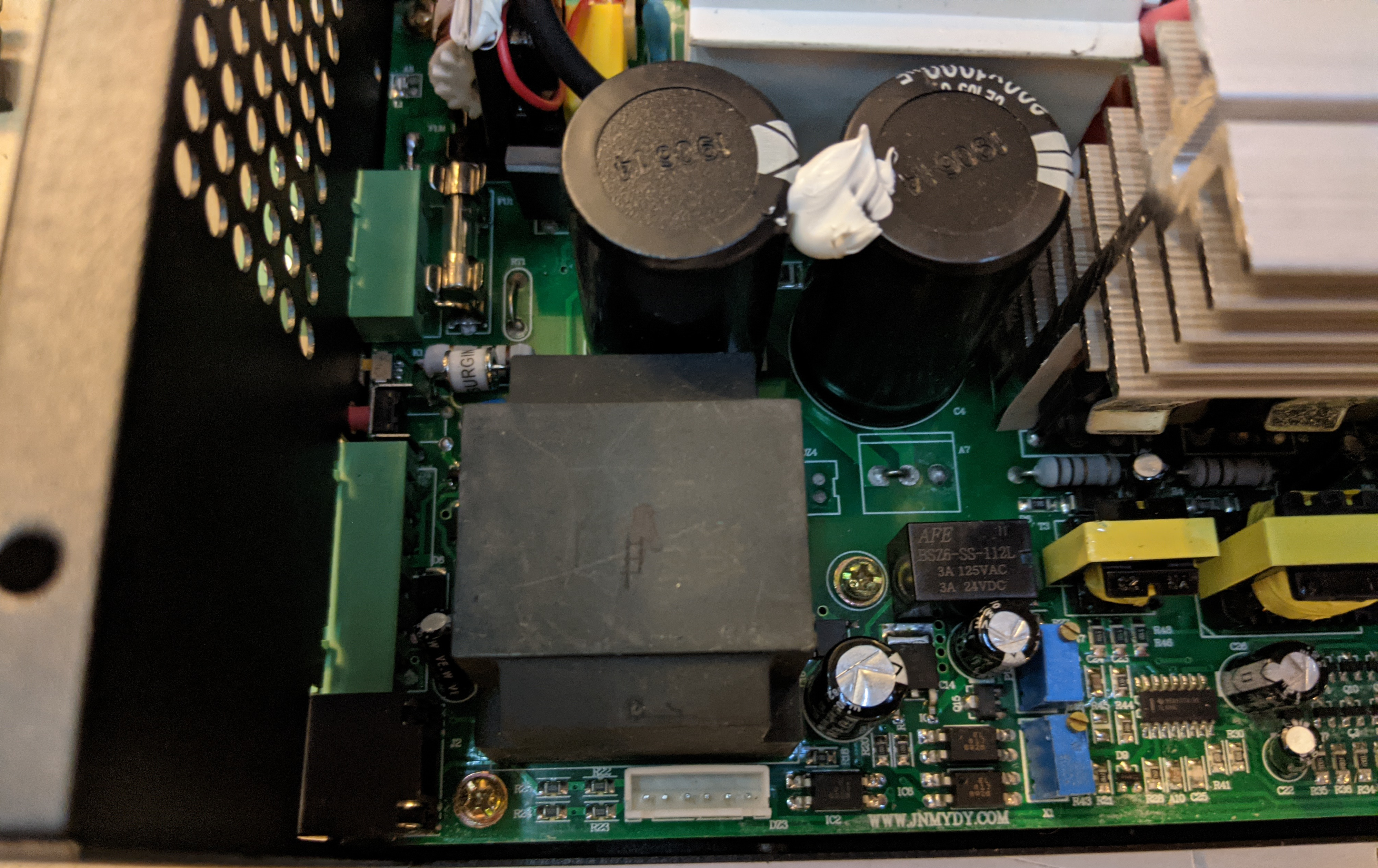
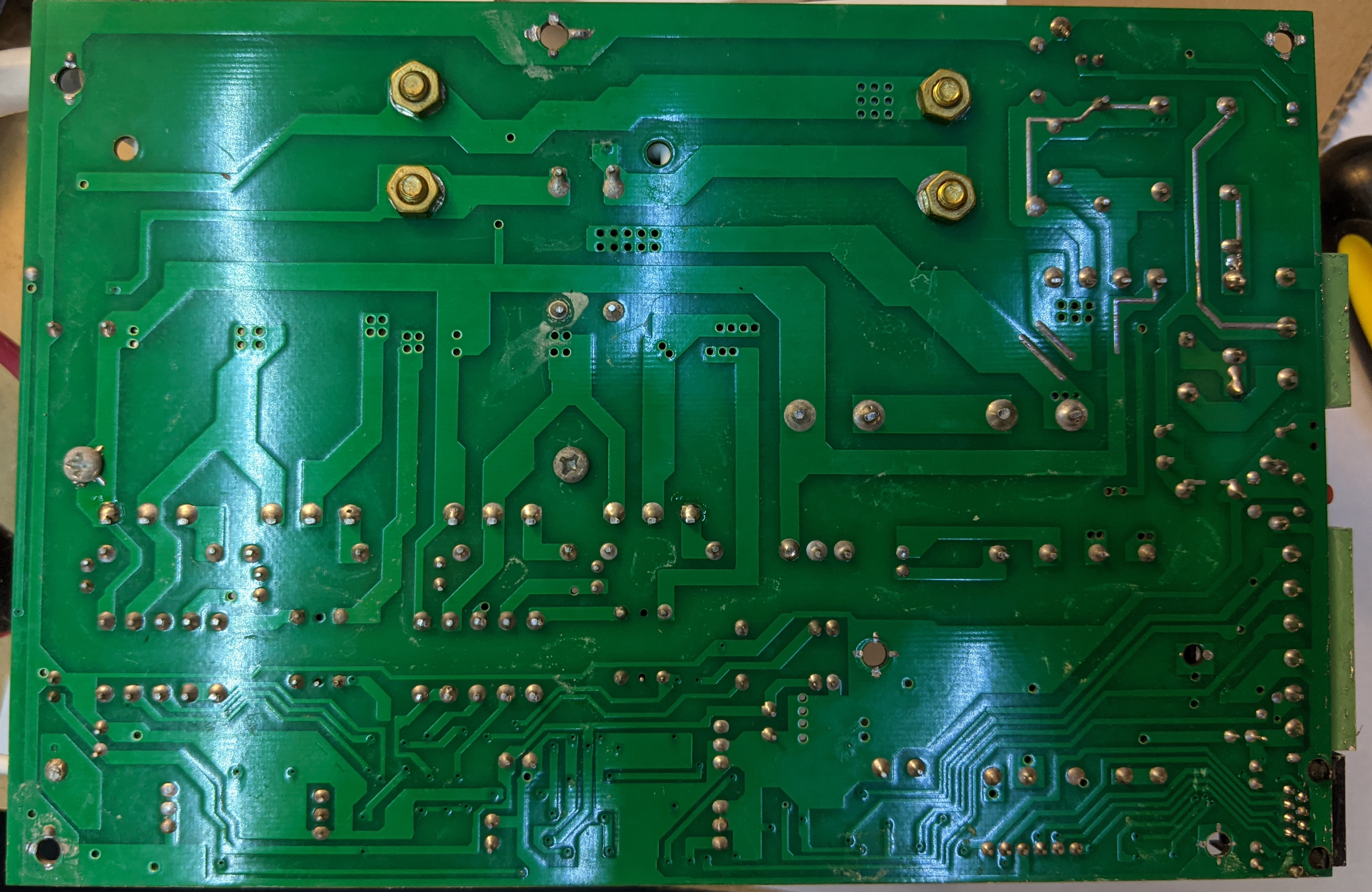
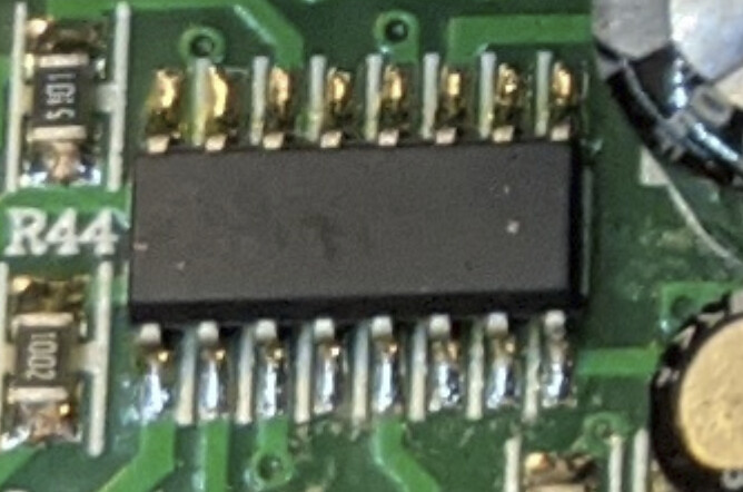
Here’s a few shots of the circuit board (sadly, the picture I thought I took of the whole top of the board I apparently failed to actually take, so that’s missing here):
The RJ-45 jack is clearly there for remote display. It shares its net with the display header.
On the bottom (sorry for the glare) you might be able to see at the lower right that the six-pin horizontal header near right on the bottom of the picture has traces going to the staggered set of eight pins on the RJ-45 jack at lower part of the right side of the board:
I already have an analog meter. That’s one of the reasons it’s hard to justify shipping (either directly for a $10 part or absorbed in a $30 price for a $10 part) a display that I don’t really need.
But it does show that I was right about the purpose of the RJ-45 port!
Yet when I use my affiliate link (above) or the direct url its $29.00
It is substituting the link for the HY-Z series when you copy the url???
I agree that $30 is to much $$$ but $15 is not bad for what it does. It shows the WP and enable circuits and what the supply is putting out. It also has a control pot.
Your analog meter will show what the laser is drawing.
I wonder if this is really a serial interface or they are just using the CAT5 for an 8 wire cable (which is what I do a lot of the time for CNC wiring).
Oh, I see what you see now that I actually click the link. $15 for the MYJG version. It’s sold by Cloudray and still shipping from China, they are just charging $5 for shipping embedded in the amazon price. I just checked, and the slow shipping that is $15 on Amazon is free shipping from Cloudray, so my rationale for not buying it was bad. Ordered direct and I’m now $10 poorer.
It’s obviously not ethernet; there’s no PHY on the board, so they are using CAT5. The RJ45 is directly wired to the same wires going to the unlabeled chip in the picture above. I didn’t trace the circuit to know what protocols are likely running across those wires. I’d guess SPI or I²C because traces are shared with the in-box display, which would basically rule out current-loop or differential serial. I doubt that it’s remoting sense resistors but I could be wrong.
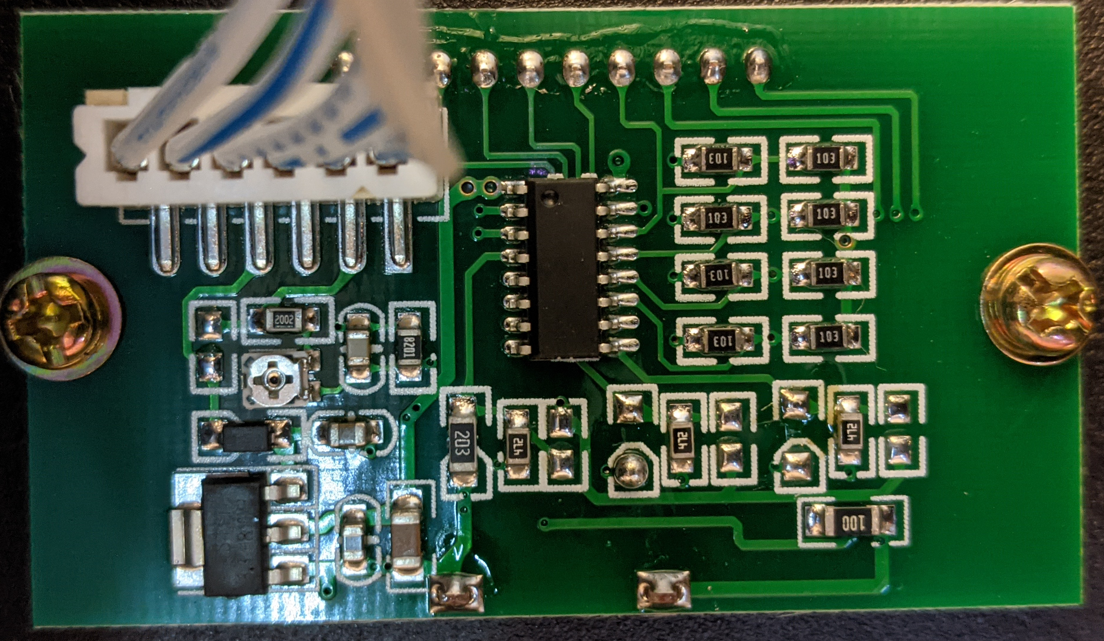
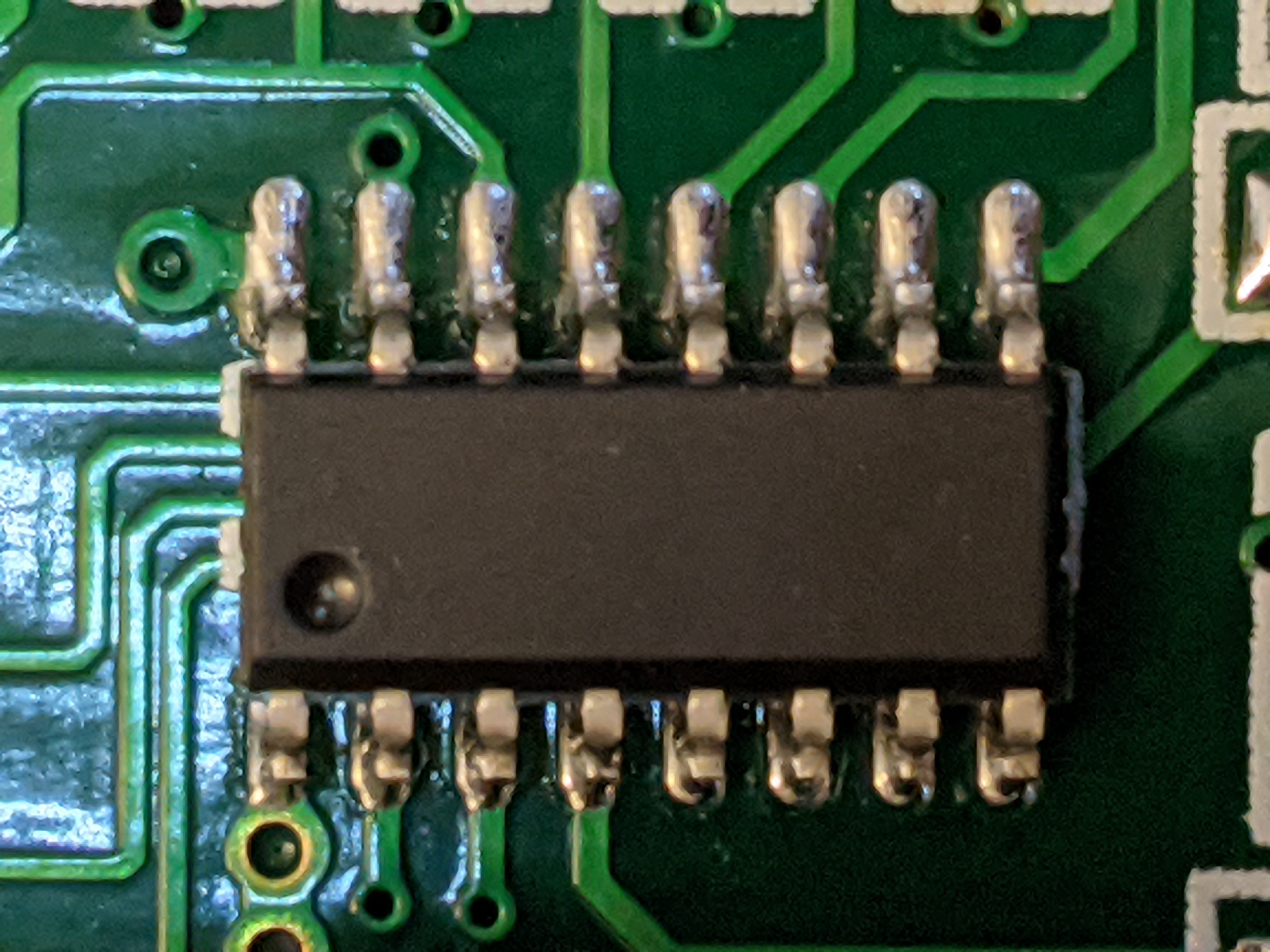
Looking at the board in the box, there’s one unlabeled LCD driver chip, and I think the contrast pot on the left is in the middle of backlight power supply drive; there’s a heavy trace from pin 1 on the LCD driver chip down to the largest capacitor on the board which makes me guess it’s VCC, and a via next to the pin opposite that I’m guessing goes to GND on the other side of the board (I didn’t unscrew the LCD board when I did the partial tear-down). All that tells me its probably a serial connection, not remoting sense voltages.
But I don’t care enough to put a scope or logic analyzer on it.
Here is cloudray’s instruction for how to use the remote potentiometer:
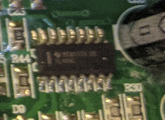
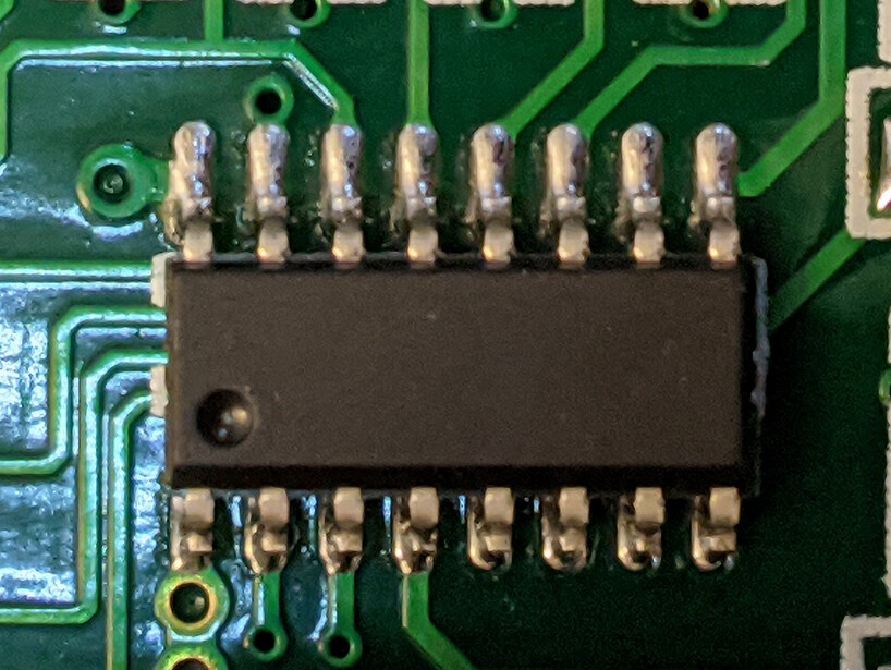
Oh, you think the 16-pin board on the display unit is just a backlight driver? I haven’t found a 16-pin SOIC backlight driver that clearly matches that pinout though.
Cloudray have already shipped the display I ordered this morning.
I was referring to the 16 pin chip on the LPS that is unmarked. I am guessing it is a TL494 pwm controller which has common use in these supplies. My guess is there is another micro in the display module to control the display… but guessing.
Now that I’ve seen how one angle completely obscured the markings on the driver on the LPS, the one on the display board might not really be unmarked after all… Might just be terrible camera work in my basement shop!