a few on the LightBurn forum have these and flashed the firmware to GRBL 1.1f so it works with LightBurn. They were out of stock for weeks but 11 went on sale recently. Only 5 left.
Get em while they’re hot: https://www.amazon.com/dp/B08FLJ39MC
a few on the LightBurn forum have these and flashed the firmware to GRBL 1.1f so it works with LightBurn. They were out of stock for weeks but 11 went on sale recently. Only 5 left.
Get em while they’re hot: https://www.amazon.com/dp/B08FLJ39MC
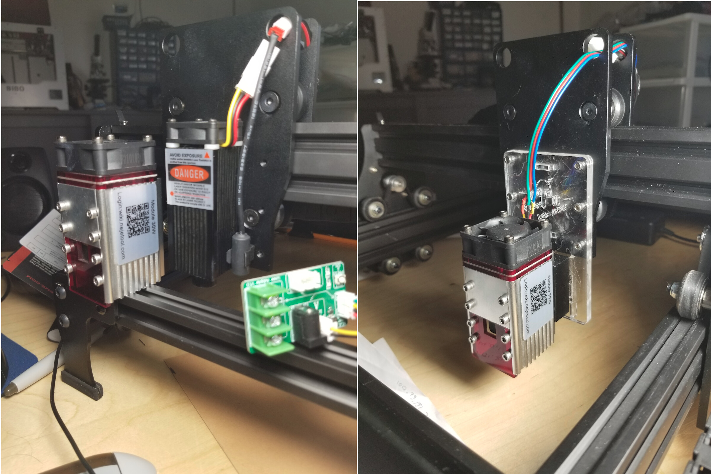
I bought one the first round when they were available. Played a little with it but seems like a great deal for the money. Need to invest in a better laser module with a little more power if you want to do more than burn stuff! ![]()
![]()
I have a “15W” module from an Ortur which is something around 4W optical. It works well for engraving on wood and for doing Norton White Tile method so I expect the 3W might work for these too.
I did a few coasters with the ‘supplied’ laser module. It actually worked pretty well.
I upgraded it to the Neje N40630 module.
This is the original compared to it’s replacement and the current mounting.
Let me know when you get yours… ![]()
![]()
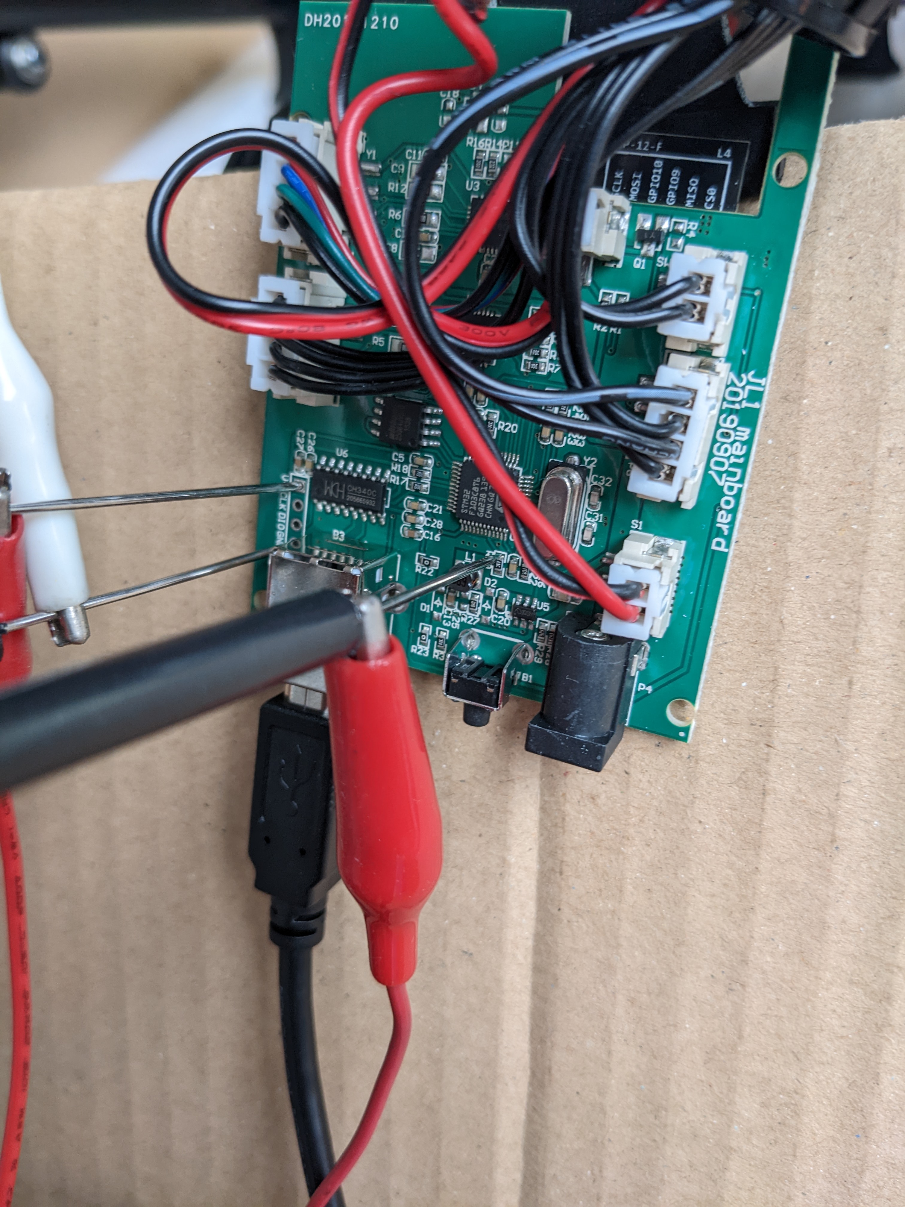
Got it but I’m sicker then a dog with a cold. It’s still in the box but I did download grblhal for stm32f1xx and built it with defaults. Hope to try and burn to STM32 BluePill tomorrow and see if I an get a GRBL prompt on the USB port.
While sick and stuck at home I installed STM32CubeIDE and was able to build the latest grblHAL for the stm32f103c8( 64K ) with a little room to spare. Had to use Release option, set optimization to Os for size, disable USB since the JL1 uses tx/rx for serial, and N_AXIS = 3 (min for grblHAL).
I’ll hook up a FTDI to it tomorrow and see if it does talk grbl to me. After that it’ll be all about remapping the IO pins. That’ll mean a new grbl can be loaded onto the JL1 albeit using stlink programmer. final step is working out the current firmware encoding so maybe a latest grblHAL can be uploaded with the existing bootloader and software(for Windows users).
I have grblHAL compiling and running on a STM32F103 Bluepill and just recently was successful remapping the spindle pwm from the default PA8 pin to PB0. Next is to start remapping the motors and endstops and see about thinning out the builtin features to shrink the memory footprint.
A bit of a PIA to get both STLink or DFU mode working on this. Mostly because of 2 things.
I was able to validate/read enough to see my board is the 128K version so grblHAL will fit just fine. Others are 64K and only a fully stripped port of grbl would fit in that space.
I will proceed with mapping the motors and endstop pins and upload grblHAL and see how it does.
It just dawned on me that it might not be too tough programming the JL1 with software DFU mode by using the 12VDC power supplied once the onboard 3.3V is found on the board to help with the BOOT0 pullup.
Without any motors connected the DFU programming could be done by powering the MCU via the 12VDC barrel jack instead of powering 3.3V via the STLink interface. What this means is you don’t need an STLink programmer to program the JL1 but will need to disconnect the motors(for safety).
holy smoly! $60
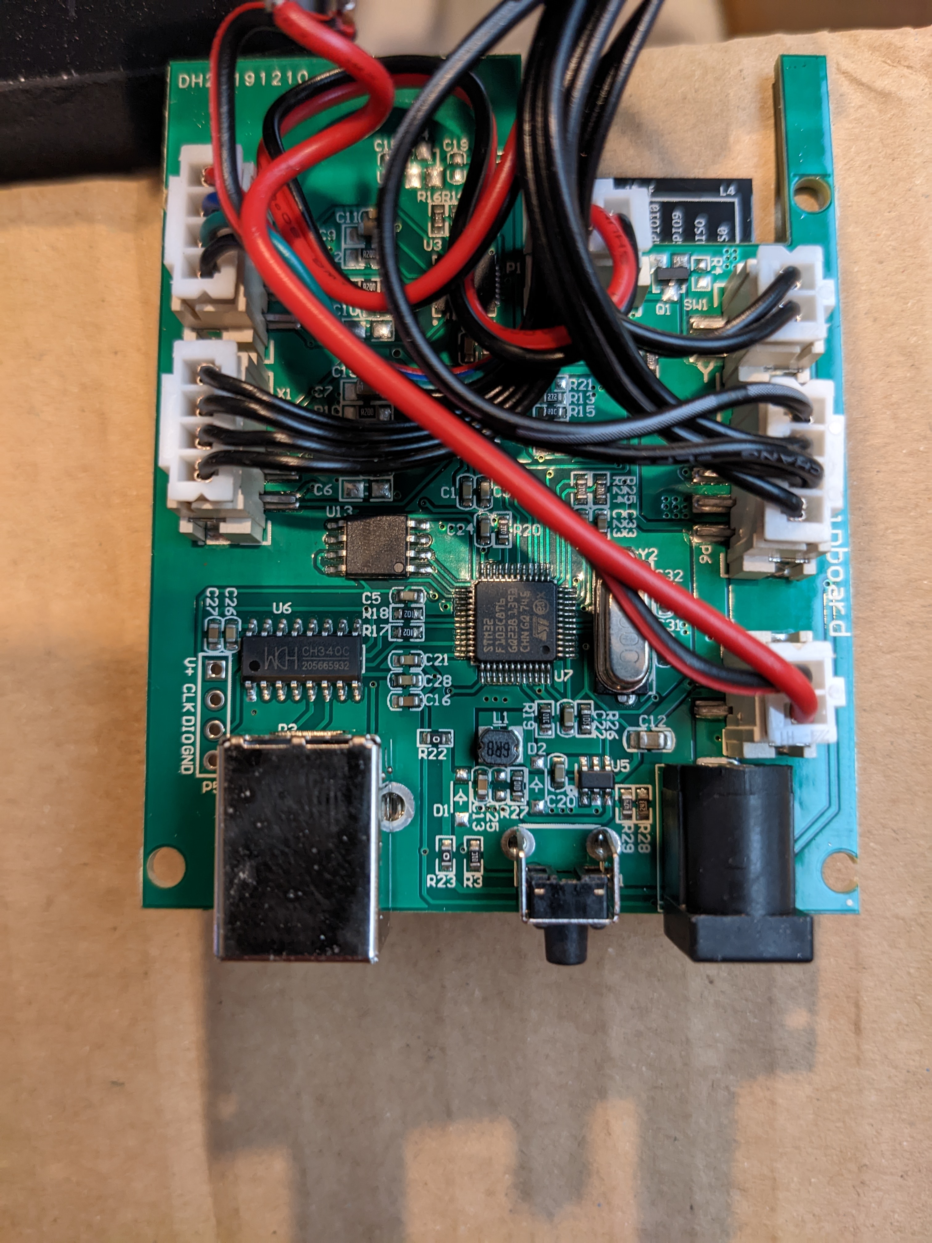
uploading open firmware just got a lot easier!
I was able to upload new firmware onto my JL1 using the supplied USB cable, the stock power supply, using the ON/OFF switch and the only extra tool was 1 alligator jumper wire and 2 frog-pokers(teasing needles).
Software used was free STM32CubeProgrammer software in UART mode. But I believe any of the many DFU mode programmers would work.
What this means is you don’t need an STLink programmer to program the JL1.
I’ve been using the firmware upload method listed above while debugging the firmware and it works great. grblHAL firmware is now functional and I know what grbl settings need adjusting to get it working with the JL1.
I get a JL2 today and should have a configuration for that soon too. And eventually a HowTo for uploading firmware.
Another option is just to wire it up to some other controller: