I’ll post pictures at least!
If the experiment works well, I would like to find the time to model it as a whole and share it. Right now it’s a mishmash of OpenSCAD, FreeCAD, SolidWorks, and What I Did In My Workshop To Work Around My Mistakes. 
If I do that, I’d like to model what I would have built, rather than things I’ve realized are “warts” either from mistakes or from silly design constraints. For example, I would change the Y stepper mount and belt path for sure.
Speaking of mistakes… I designed kinematic mount blocks that I’ll attach to the bed. Two of them have reference features (chamfered hole and slot) that need to match the locations of holes I drilled in the “frog” that holds up the bed. But I accidentally calculated the locations of those features in a way that would barely work on the 220mm nominal bed width of the original bed that came with my old printer, and not the 224.4mm wide piece of cast aluminum I have as the actual bed I’m using. I actually had them 6.4mm too narrow due to another mistake, but that I could have made work. So back to the shop to machine a few more parts!
…I forgot to lock the head on the mill before profiling, so I got the opportunity to do the profiling twice! But now I have kinematic mount blocks that fit.
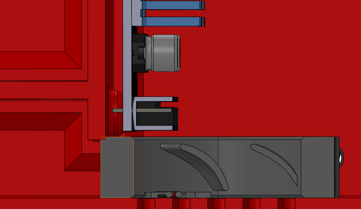
Then there was the mistake I made long ago of drilling out what were supposed to be M5 holes with a 4.5mm drill bit instead of a 4.2mm drill bit. I determined that M6 acorn nuts would engage just fine in the chamfers I made in the kinematic mount blocks, but fortunately before I drilled the holes out with a 5mm drill bit to tap M6, I checked whether I had any of an appropriate length of M6 screws handy.
Instead, I wrapped some M5 screws in just one turn of teflon pipe wrap, then used loctite blue 242 in the holes and inserted the screws loosely in the holes. Should be cured by tomorrow evening, and hopefully it will work as “poor man’s helicoil” for this. I’m planning to use more teflon wrap when I install it for real, so it should be nice and tight and not wander. I hope.
It’s been over two weeks since I last summarized a “final” (hah!) punchlist.
- Design, fab, and attach an extruder mount
- Assemble and mount bed mounts
- Print new ninjaflex “shoes” for the feet; the first set don’t stay on when I move the printer.
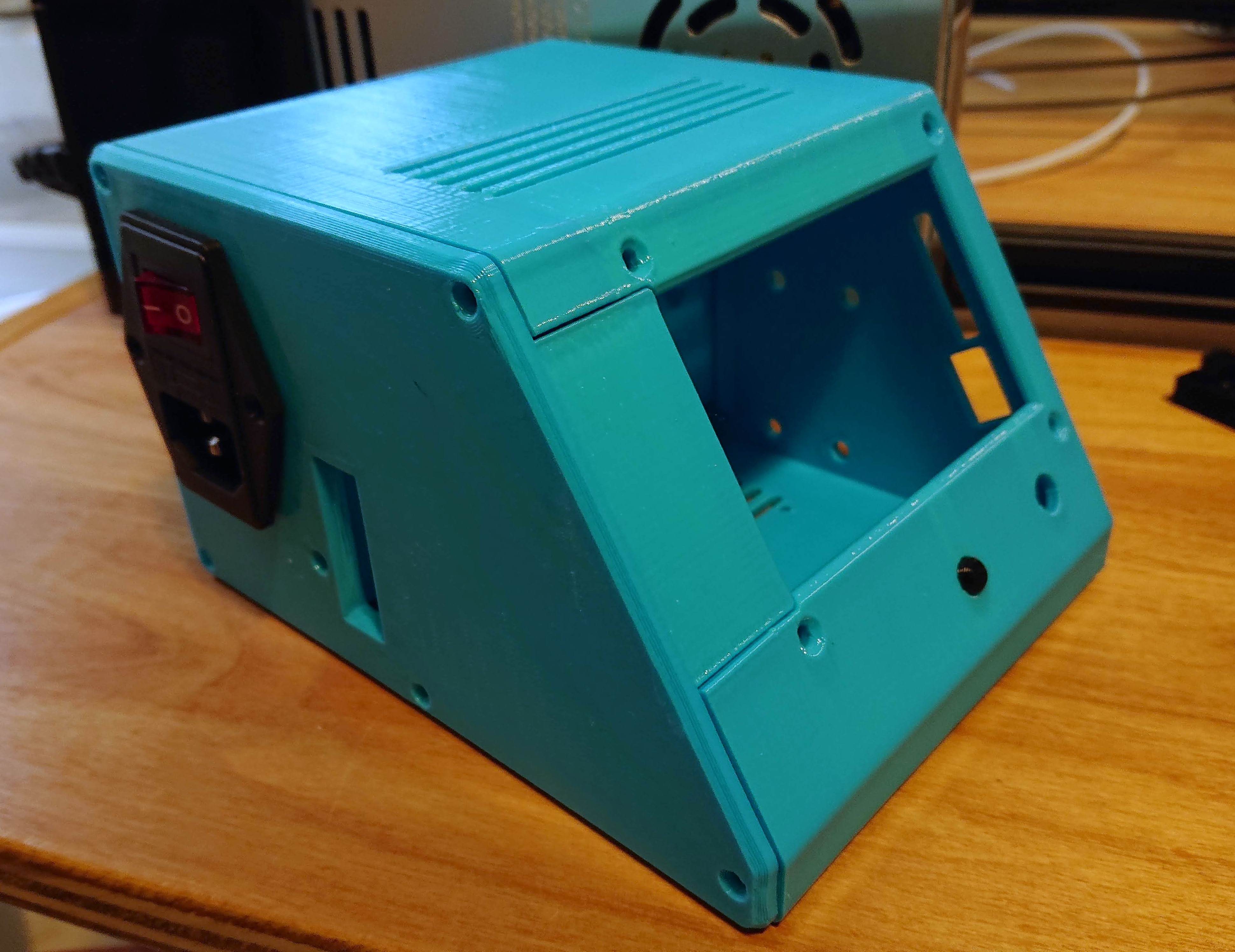
- Wire up electronics, including TCO glued to the silicone heater with RTV for when the SSR inevitably fails.
Things I can think of so far that I would do differently if I were starting over:
- Make the length (Y) as long as the linear rail I’m using. I got lucky and aligned mounting holes in the linear rail with the front and back extrusion, but next time I wouldn’t have it sticking 25mm out the back. The middle extrusion really probably isn’t needed. Similarly, just cut the X cantilever the same length as the rail; it won’t hurt to balance it.
- Model the hotend and extruder I’m going to use accurately before I start cutting aluminum. I still haven’t figured out how I’m actually going to mount it.
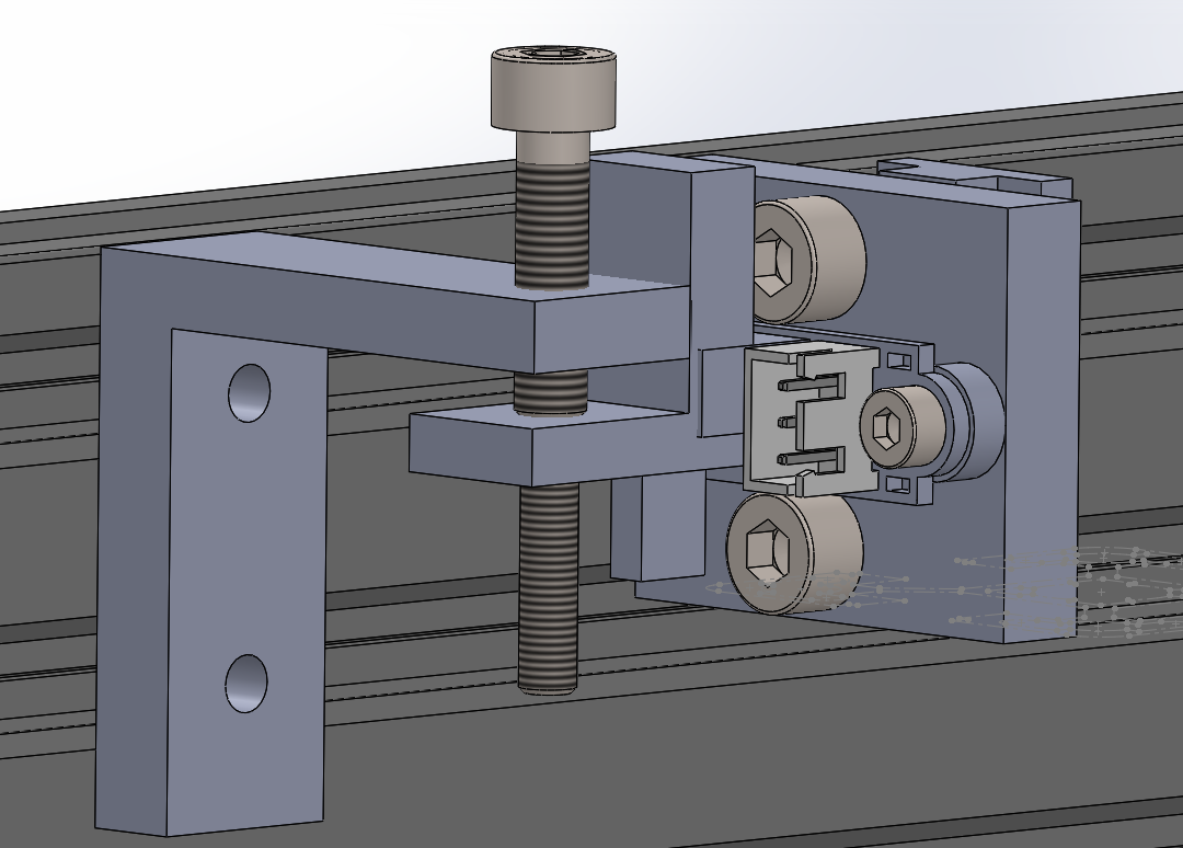
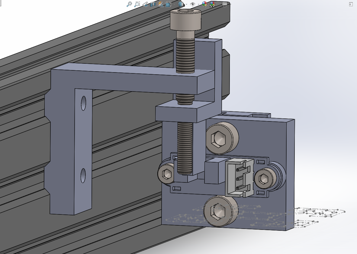
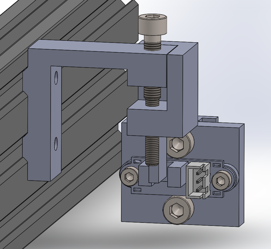
- Design the Z lift plate so that the X motor mounting screws aren’t buried between the plate and the X extrusion, moving the motor forward.
- Redesign the X idler mount pieces to be triangular and to have two nuts each into the extrusion.
- Use 4040 v-slot for the tower instead of 4040 t-slot.
- Consider changing the Y motion platform to use a vertical motor and openbuilds stepper motor mount plate
- Tap all the exposed ends of the extrusion M5 just in case I want to use them later.
- Plan to move the bed mount higher above the linear rail block. I used 6mm spacers to move it up, but that was a hack after the fact. There are multiple better ways.

 I’d appreciate the benefit of your experience here. I’m (still) printing on glass because my PEI bed has reportedly left China a week ago but hasn’t yet made an appearance in the US, which probably means stuck in customs.
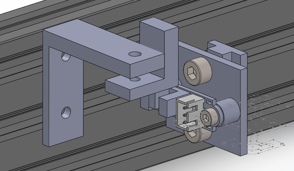
 If I single point it, I’ll actually make both holes the same diameter (an appropriate minor diameter cutting 0.8 and 0.9 mm threads in whatever piece of brass rod I find in my shop probably), and then just cut different non-standard thread pitches, one in each end of the rod.