Cantilever printer design based on leftovers

I’m at home because pandemic (I am very grateful that I am working from home!) and I just got my corexy build starting to work well. In particular, it’s now working better in every respect than my junk gantry hictop printer that got me into this 3d printing world in the first place.

But when it comes to printing emergency protective gear, could I do more, faster?

I became curious: Could I, with leftovers and excess stock sitting around the house from other projects, together with parts from the existing gantry printer, make a substantially better gantry printer? From the previous rebuild, I have a couple of 450mm MGN12 clone (“chiwin”) rails that work. From another project, I have an extra 330mm 1204 ball screw. I’ve come up with a design I can build with buying only a small 100 tooth GT2 belt; everything else is sitting around the house. (I think: I haven’t measured to make sure I have all the necessary lengths of extrusion; but there’s enough flexibility in the design that I’m pretty sure I can make it work anyway.)

I’ve been messing around in OpenSCAD for the design, so I don’t have a STEP or IGES file. I’ve only roughed out most of the hardware (e.g. hot end, bearings, ball screw and nut) just barely enough to be confident of size and fit. I haven’t modeled many of the parts; extruder, bearings, pulleys, idlers, belts, drag chain, wires, fans, or electronics in general; I just know where those go, at least where it matters, and am now pretty confident it can work.

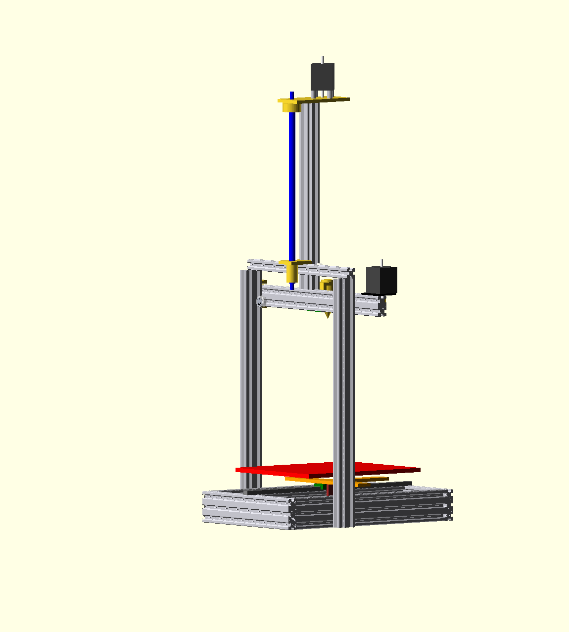
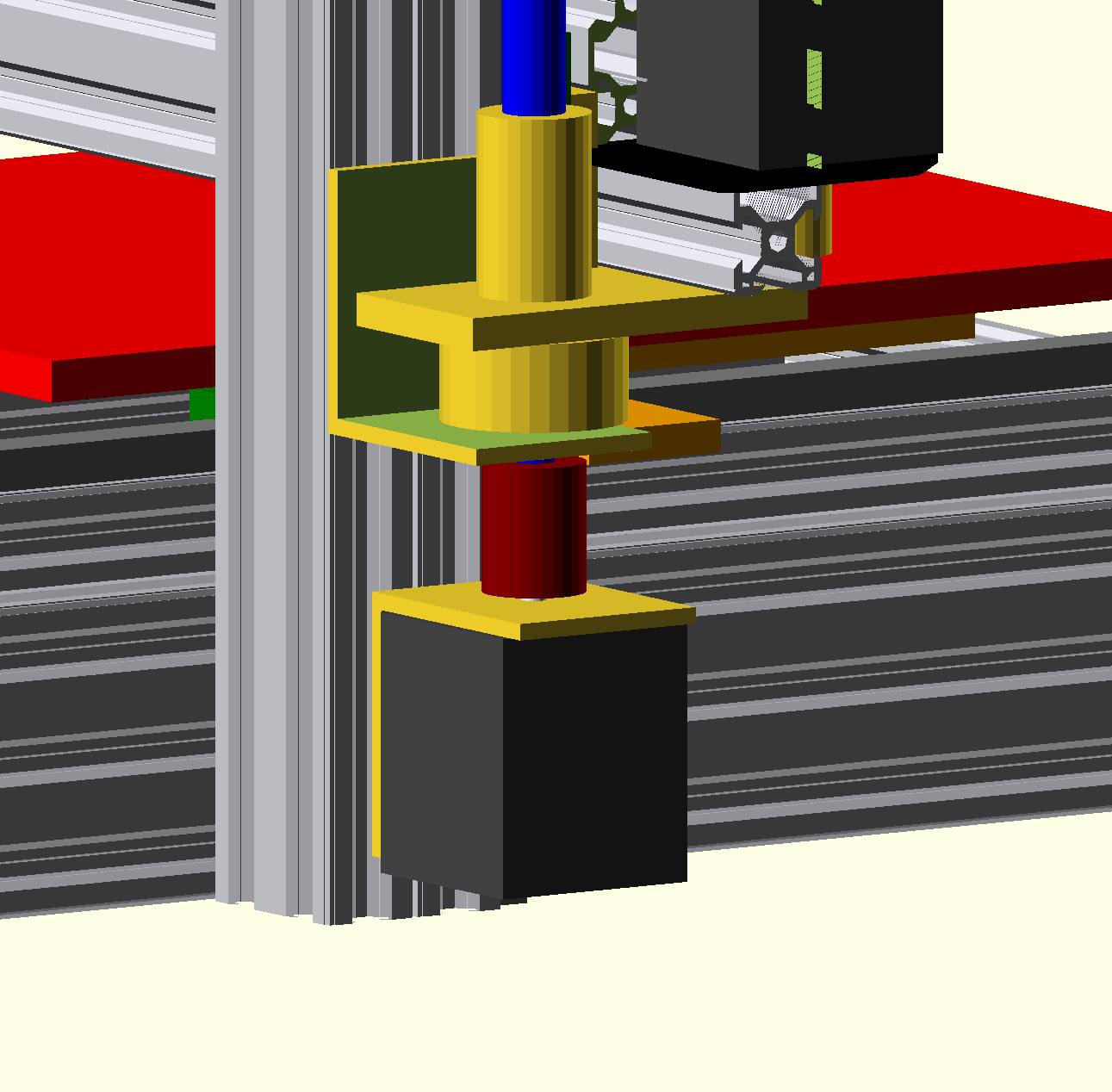
I tried to avoid an overconstrained design. I used one motor per axis, with no need to transfer synchronized motion. It is designed to enable an enclosure that is at the top of the fixed gantry; the lead screw and pillar of the inverted T would go through and stick out the top; that’s why the Z motor is mounted on top instead of below the Z gantry plate.

I haven’t seen this “inverted T” single-screw gantry printer approach before. Has anyone here seen a gantry printer with this design?

It’s designed for a kinematic bed mount. I do have parts on hand to make that work though I might choose a different design that requires ordering a couple more parts.

Here are some pictures, including animated gifs, to show what it looks like:

First, an animation of all three axes moving simultaneously:


rotz

rotx

With the gantry raised to max Z, front and back:

4 Likes

What are the advantages of a single center Z axis? I guess I should ask about using the design above instead of the “standard” one?

A lot of gantry printers have a lead screw on each side of the gantry and then have to do something to keep them in sync. The better ones use a belt; the junk ones use two motors (which will get out of sync when turned off because of microstepping even if all other potential problems are resolved).

This one uses just one screw. The downside is that it the screw and middle post of the inverted T use a lot of vertical space that isn’t used on normal gantry printers, but outside of print farms, how often is the space above a 3D printer actually constrained? :slight_smile:

But one advantage is that I have the stuff at home to make it. The dual lead screws on my old gantry printer that will sacrifice some parts are a little warped, and I don’t want to reuse them on a replacement printer. And I have one ball screw. :slight_smile:

1 Like

After I submitted the question, I realized how it actually worked and rewrote the question.
At first it looked like the center lead screw moved independently of the horizontal plane but then I saw that it was the drive for the Z axis. Does that put a lot of leverage on the base (make it top heavy) when at its maximum point?

…and then I saw your edits, and raised you a better answer… :wink:

If anything, it should be more stable, I think. All the substantial moving load, the bed, stays low and doesn’t move. And if you’ve ever balanced a pole upright on your hand a you’ll know a long broomstick is easier than a short pencil because inertia works in your favor. So yes, if something were actually pushing the top in the Y direction it would have more leverage, but I don’t think it’s something to design for.

The weak point I can think of is racking near the top so that the Z height is inconsistent from side to side, and is the first place I would see wear in the Z guide wheels. But most of the inertia there is directly side to side as the head moves, closely assigned with the lower Z guide wheels, so I don’t see a substantial source of racking force. I might be wrong and have some possible mitigations in mind if it occurs though.

1 Like

I edited the post to start with an image of the printer moving all three axes simultaneously. That probably gives a much better sense of how it works than the previous renders.

1 Like

And of course your better answer came after my reply! I need to just check the forum a little less often so that I stop replying before I see the whole picture! :framed_picture:

2 Likes

That bed looks like it might get wobbly side-to-side. Am I misunderstanding it?

1 Like

The “frog” on which the bed is mounted is itself mounted on MGN12 rail. It might look like the bed should be mounted on two MGN12 rails side by side, but there would be at least two problems:

  • It’s over-constrained, so any imperfection will lead to binding
  • More specifically, even without imperfect mounting, thermal expansion will cause binding.

In my corexy, I do run two rails for Y and suspend X between them, but I have a sliding joint between them to resolve the overconstraint.

In practice, people do put gantry printer beds on a single MGN12 rail as upgrades.

I could upgrade to MGN15 or MGN20 later if MGN12 is a problem in practice. But I don’t have that sitting around the house, and it’s almost certainly substantially better than the LM8UU bearings loose in bearing blocks on the donor printer. :slight_smile:

2 Likes

Personally I would just drive it from one side and let the other side be cantilevered, works fine on my Ender3 with zero issues but it really depends on how wide you’re going. Another option would be most boards have an output for a second extruder, you could always instead use that for dual z motors and Marlin now has the ability to home each side independently to tram it to the bed. Pretty slick setup.

I’m an adherent to the Mark Rehorst “If you design it right, it stays tram” school of design. No extra drivers on the board anyway, so a moot point given my self-imposed constraint. :slight_smile:

Regarding making it cantilevered, it’s a 224mm wide bed (reasons) and I think about arm deflection as the cube of the length. But yeah, that would probably work fine here. I’ll ponder more…

I have a third piece of 450mm MGN12 in which I replaced all the ball bearings, and the new bearings were slightly larger. I worked earlier to alter the rail to fit the new bearings. I probably got it loose enough to use for Z; the carriage is tight but doesn’t take much effort to move. That would get rid of using any of the openbuilds wheels. I could still drive it with the ball screw, but the motor would be at the bottom and the screw would stay in one place.

What I don’t have the tools to do, or don’t know that I have the tools to do, is calculate the deflection of the 2040 (or 2060, I could do that too) v-slot arm with some (unknown now) hot end and extruder mass at ~250mm station (depends on exactly how I mounted the Z linear rail). I just know that it’s dominated by the cube of the length of the arm… @Eclsnowman you’ve done more design than me, do you have knowledge and data enough to calculate deflection? I’d have the mass of 335 mm of v-slot, 255mm of MGN12 rail, and (say, a max of) .5kg hot end at max 250mm station. Is this something you can just load up into solidworks or fusion360, assign materials, and click a “FEA” button somewhere, and have it just do it? I’m quite clueless here. :frowning:

1 Like

I’m still working out how best to attach motor and Z screw nut best for the cantilever design, but that’s no big deal; if I don’t think of anything more clever, I have some 2" square aluminum tube I could make work. @Eclsnowman is this what you had in mind? (I put a block to represent an extruder/motor on the hotend to visualize the extra cantilevered mass that I didn’t worry about with the gantry design.)

1 Like

Yep I think that would work, the only thing I might do is add another tower on the other side and then even just one v-wheel (3 would be better) on the other side to guide it so you don’t get the cantilever arm whipping with harmonics (during infill or gap fill).

1 Like

I need the extra arm length to hold the X idler bearing, so there would be room to add three wheels and the extra tower if I need it to damp harmonics in the arm.

For statics, I just found (that is, finally bothered to do a search) that someone kindly put up a spreadsheet:

A 1kg concentrated cantilevered load at 0.3m station on 2040 v-slot should deflect 0.03mm according to that spreadsheet. If I change to 2060 v-slot for the arm, that goes down to 0.01mm deflection. I would just have to do something different for the X motor mounting, but I can imagine a few ways to do that.

For dynamics, I’m pretty lost. I guess Z axis harmonics are the major component you are suggesting, because all the moving mass is on one side of the beam. It is, however, bound to a rail made of bearing steel. I wonder if that would change harmonic characteristics significantly? I wouldn’t be surprised if the frame contributed more just from the mass of the moving bed when doing infill/gap fill.

Anyway, if I do the cantilevered version, I’ll start without the second tower as an experiment, and it’s a few minutes work to add it if I do need it.

I can’t ignore the static deflection of the tower, either. Leaving that as 2040 v-slot seems unwise. I don’t have 4040 v-slot but I have some recycled 40mm t-slot that is solid; probably more than the 4040 v-slot would be anyway, and I can work out all the mounting hardware I need for it. Also, I bought it from a scrapyard on a whim and then wondered what I was going to do with it, so happy to put it to use! (I don’t have a model for the t-slot, so I’m just mocking it up with two 2040 vslot sections.) Here’s an animation with 2" square tube for Z screw and motor mount, 2060 X arm, and 4040 Z tower.

3 Likes

A minor thing, but I always prefer the motor on the bottom of the screw, because gravity helps keep it in place. Similar to your “if you design it right…” comment.

Not sure what you mean by “gravity helps keep it in place”; it wouldn’t be sitting on the table in any case. The screw is fixed in the XY plane by a flange bearing represented by the fixed cylinder on the top of the square tube there, and the motor is screwed to the same fixed tube. I was planning belt drive allowing for various drive ratios.

But that’s not really important. There is room. I’m not really using motors that long or dual-shaft motors, I just wanted to visualize enough room to not have to worry about what motors I might some day put in. I should look through my scrap bin for parts to mount it for direct drive. I think I have some 2" aluminum angle and I could use two pieces, one for the flange bearing and one for the motor. I have the necessary couplers, and it would be simpler. And it would get rid of the need for the only “vitamin” I don’t already have, the 200 tooth GT2 closed belt.

So thanks for the push!

I was simply referring to this latter design’s Z-axis screw held to the motor with a coupler.

When you had it inverted (motor on top), the mass of the X-axis would be pulling down on the screw, which can stress the coupler holding the screw to the motor shaft, and could lead to it slipping off over time. This is effectively a non-issue with the motor on the bottom.

1 Like

Ah! One of the things I don’t like about the junk printer that this is intended to replace is that it loads the couplers axially. They are fortunately loaded in compression, not in tension, but even better is to transmit only radial movement, not carry axial load.

It’s not necessarily super obvious from the animations I posted, I expect, but none of my designs in this post so far use a coupler to connect the motor to the Z screw. They have all support the screw on a bearing and use a belt to couple the motor to the screw. I didn’t model the belt, I just made sure the path was clear for it.

I think I’m going to switch to direct drive with a coupler, but the screw load will be on the bearing not the motor; the coupler won’t be loaded axially (here, in the Z direction) at all.

My corexy has the motor driving a long belt, which also goes around the two Z screws to move them always synchronously.

Thanks!

2 Likes

I have 1.5" angle but that’s not big enough, so I can cut off 40mm of the 2" square tube and cut it into two pieces of angle, each of which has one side that is fully 2" long and the other side is 1/8" + kerf smaller, which won’t matter. Then I can mount the motor on one piece and the screw flange on the other, so they are both supported and the coupler (dark red here) has only radial load, not axial load. There’s plenty of room.

So now I don’t need to wait for a belt to arrive.

I don’t think I’ll cancel the order; I still have a bunch of different sizes of GT2 pulleys, and if I end up deciding I want a different drive ratio, I can go back to belt drive. Or I’ll use the belt for another project.

I’ll have to be careful to cut all the holes in the right places, and assemble the parts in the right order, because there are lots of order of operation assembly constraints. If I were designing this with different constraints from “what’s in my scrap pile” I think I could design more for ease of assembly. :slight_smile:

2 Likes

Nice! I should add that I am living vicariously through you with this. I have parts from my first Printrbot LC Plus and my Printrbot LC Plus v2 that I was planning to cannibalize along with some Misumi 2020 extrusions I bought years ago to design and build a new 3D printer. Right now I have a roughly 75% complete design in FreeCAD and (surprisingly right now, I’m sure) not enough time to finish it. All of my maker toys (3D printer, CNC Router, K40 Laser cutter) have all been gathering dust roughly since my daughter was born about 2.5 years ago. She’s a blast, but she has put a kink in my “maker style”. :wink:

3 Likes