Using your test results below:
We need to get consistent on our labels and configuration for each of these test so we can insure that I am not confusing the results. My guess is that there is some thing in the wiring or configuration that is keeping the L’s PWM signal from proper control.
The LPS Test button should work. On these supplies the LPS Test overrides all other signals and acts like the “L”. I think this is a hint?
Lets use these terms:
Control Panel Test Button = CP Test
Laser Power supply test button = LPS Test
Laser enable button on K40 control panel = Laser Enable
For each test we need to verify configuration which is:
Software:
Controller:
LPS L connection to:
Laser enable from controller:
Revert back to stock wiring. Laser fires through software and on front panel test button. Does NOT fire on LPS button, but I can live with that.
Note: This is improper operation for the LPS.
Software: whisperer
Controller: Stock
LPS L connection to: stock controller
Laser enable from controller: none
Grounded L on 4 pin LPS connector. Laser fired as expected.
What was the configuration?
Software:
Controller:
LPS L connection to:
Laser enable from controller:
Measured RAMPS D8 to Q3 drain - good circuit. Q3 Source to ground - good circuit.
Not sure what you mean. That D8 on the output is connected to Q3’s drain?
Q3 source to to ground? The source on the mosfet to ground should read as open. It needs to be an “open drain”. That means that the source is not connected to a pullup or ground or anything. The drain of the MOSFET should connect directly to L on the LPS?
Connected 24v to RAMPS input. Connected L to D8 (Q3 drain). Connected 4 pin LPS connector ground to a RAMPS ground.
Make sure that nothing else is connected to D8 especially a pullup to any voltage. I think this is configurable on the board?
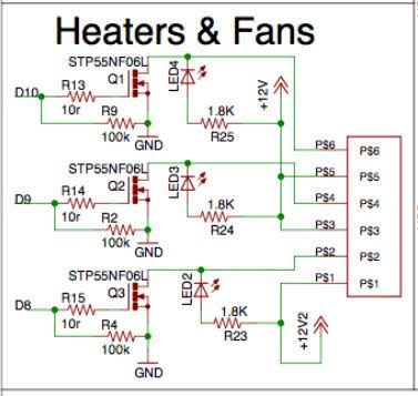
Fires on front panel test button, but not software. LED 2 did not light when test button was pushed, *[Which “test” button?] however this takes +ve supply from 12V2 (the 11A supply) which wasn’t connected. *{The MOSFET must not have ANY voltage connected to its drain!]
What is the configuration:
Software:
Controller:
LPS L connection to:
Laser enable from controller:
I changed the RAMPS config to use D9, which uses the +12V supply that is connected (24v from the LPS actually).
In our configuration there must be NO supply connected to the driving MOSFET’s drain.
This time, when the test button is pressed LED3 lights up, and the laser fires. No fire from software though.
Is this the CP Test button?
My guess is that the CP test button is driving LED3 to ground through the LPS this means that the CP test connection () and L are connected internally. This is normal for this supply.
The key question is why does D9’s LED 2 not act the same?
Back to stock, K40Whisperer works fine.
That’s good then we know we have a wiring or software config problem.
Next post will be a schematic that we can reference for better understanding.