I have bought me a
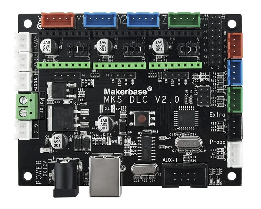
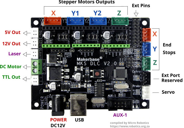
MKS DLC V2. 0
MKS CD V1. 0 stepper Breakout board
DQ420MA Stepper drivers.
I connect it up download grbl and open up openbuilds to test but no movement on my x, y or z
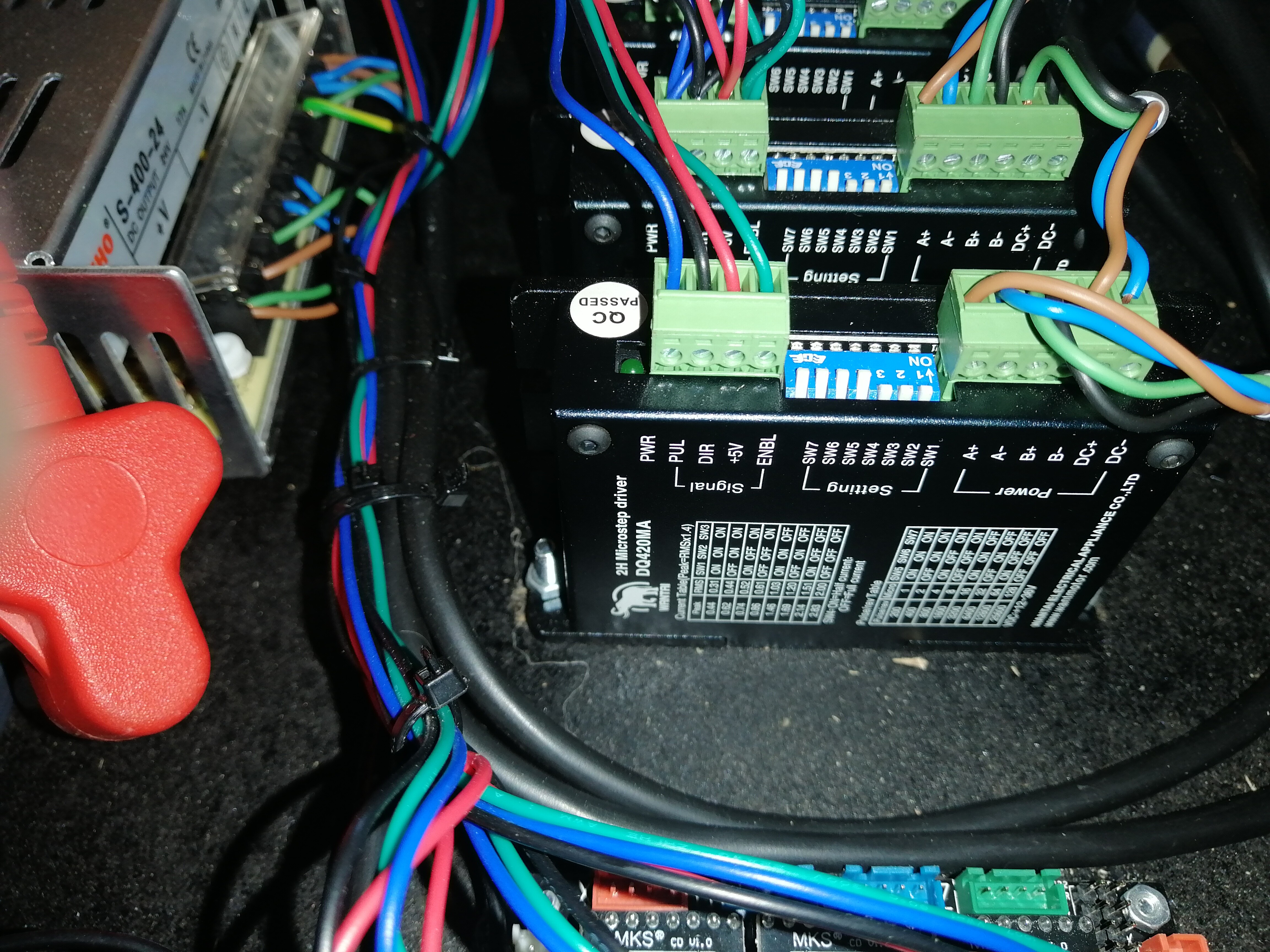
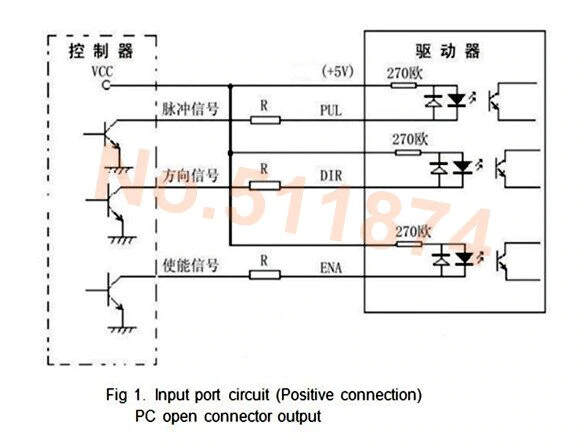
How do I Connect the DQ420MA stepper drivers Signal pins to the MKS CD V. 1 breakout board pins
I have it as
En - Enb
STEP - Pull
DIR - Dir
+5v - Grn
As advise by the supplier. Does not look right to me. Do I only have to upload the GRBL and the machine will run or do I need a code. Can someone help I’m new to this and really need help as a beginner
MKS DLC V2.0 needs to be driven over USB; it doesn’t have storage of any form.
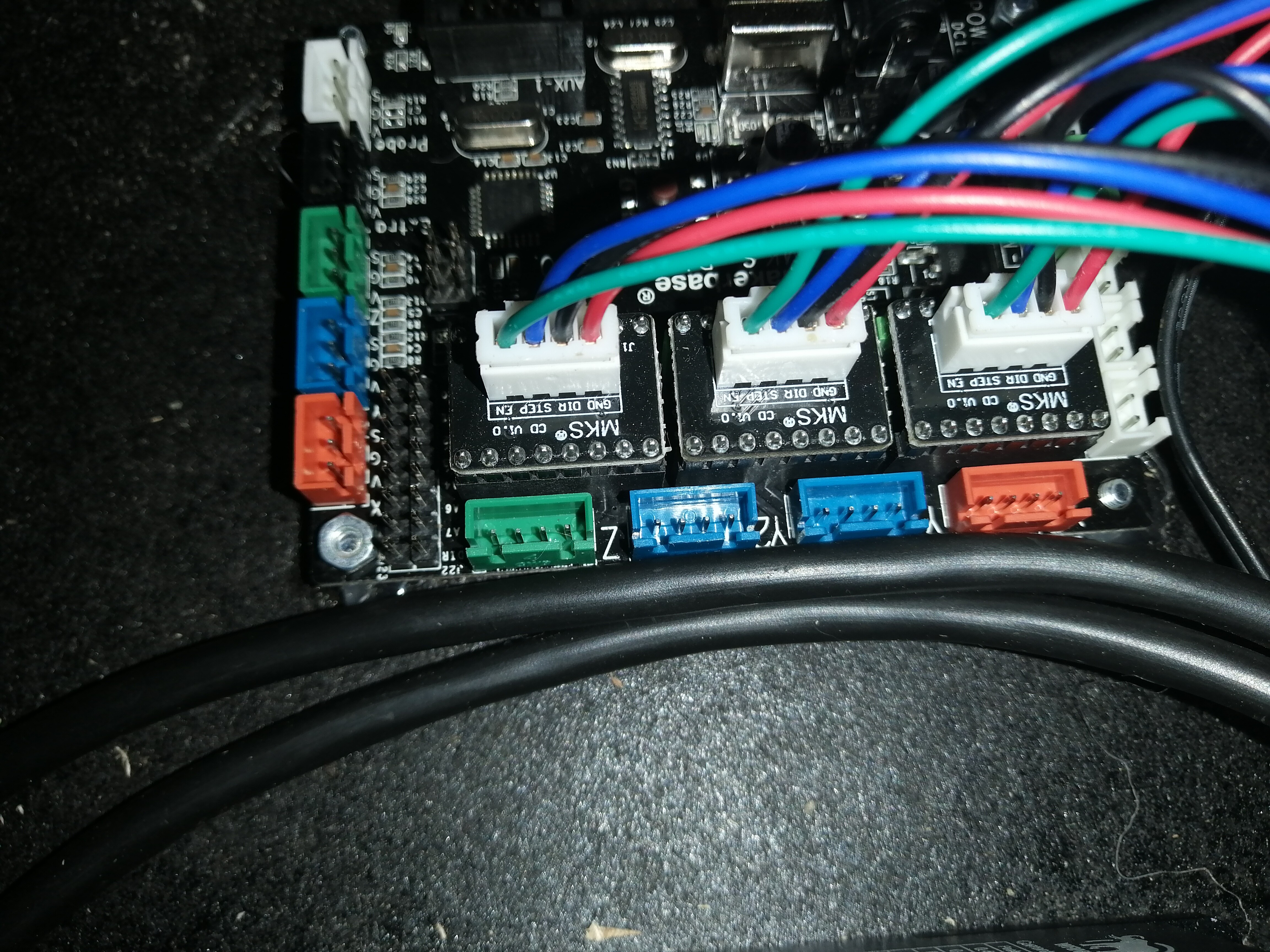
I don’t have an MKS stepper breakout board. I don’t see why you would need one. The MKS DLC V2.0 has the signals brought out on a separate header right next to the step stick headers. The breakout is for boards that don’t have headers to break out the stepper signals. I have an MKS DLS V2.0 and I have the stepper motor drivers connected directly to the headers.
Hi thanks for the advice on the breakout boards. Can you please assist me with the wiring from the MKS DLC V2. 0 TO the stepper drivers DQ420MA. I have connected everything and upload GRBL 1.1 But when I go to CNCJ nothing happens when I try to move x, y or z… All the motor stand stil no movement
I don’t know about the DQ420MA drivers you have. I’m using logic-level LV8729 drivers.
Typical DQ420MA units I see are opto-isolated with six control connections. In that case, you might want to build the firmware in open drain configuration, and then:
+5V goes to EN+, PUL+, and DIR+ (these might be labeled in various ways)
No idea then. If it were mine I’d ditch the breakouts and send +5V to the pin labeled +5V and build the firmware to use open drain for the signals — but I don’t have any documentation for the stepper drivers you are using.
Given that your supplier suggested you buy the breakouts to replicate the pins that already exist on the board, it seems possible that they also got something else wrong.
Look at those groups of four pins directly underneath the green header blocks for the step sticks labeled EN STEP DIR GND:
Those are the same connections that the breakout boards are providing. The breakout boards are for other control boards that do not provide those four pins already.
@donkjr do you see anything I’m missing here? Do you see a possibility other than open drain?
There is a lot that could be wrong here including power, firmware, driver connections, etc.
did this configuration ever work?
have you tried this with internal drivers vs external drivers to see if the rest of the system is working.
If not I would get at least one internal driver module and see if you can make one axis move.
Measure continuity between the output pins on the MKS CD V1.0 and the equivalent pins on the motherboard just in front of the green inline connectors to see if the module does what we think?
Thanks for all your input. I have also thought that the GND to the +5v does not look right. As my commonsense as electrician it is not correct to connect GND to a positive it will cause a short. I even have the suppliers technician here for six hours and he did not came right ever. And he have advice to exchange the DQ420MA for the BT6600 drivers. He could not get one axis to move. Thanks for all of your advice it help me a lot. I will need the wire diagram for the bt6600
Nothing is working you are 100% correct how will you suggest I must connect. I think to remove the GND and connect the 5 v from the MKS DLC to the +5v. Will that work. I also think the GND to the +5v could not be correct. I was advice by the suppliers technician to swop the drivers for BT6600 after he could not get it to work
This configuration never work. Not even a 1mm movement. Nothing have worked not even the suppliers technician could get it going. I have asked because my commonsense told me the GND to the 5v can not be. It is the same to connect life to neutral and that will cause a short.
Am totally new to this. Have only electrical experience as an Electrician. This is my first time. And I need guidance. I’m gone swop the DQ420MA FOR THE BT6600. I still have the MKS DCL 2.0 and I upload GRBL 1.1 with Arduino 1.8. Please help me to run the machine.
@Werner it’s no problem that you are new at this. However for us to provide the best help it’s important that you read, follow and report back on the progress of ALL the suggestions that are provided to you in these threads. It is also important that you answer all the questions and tell us about any changes you plan to make before they are made.
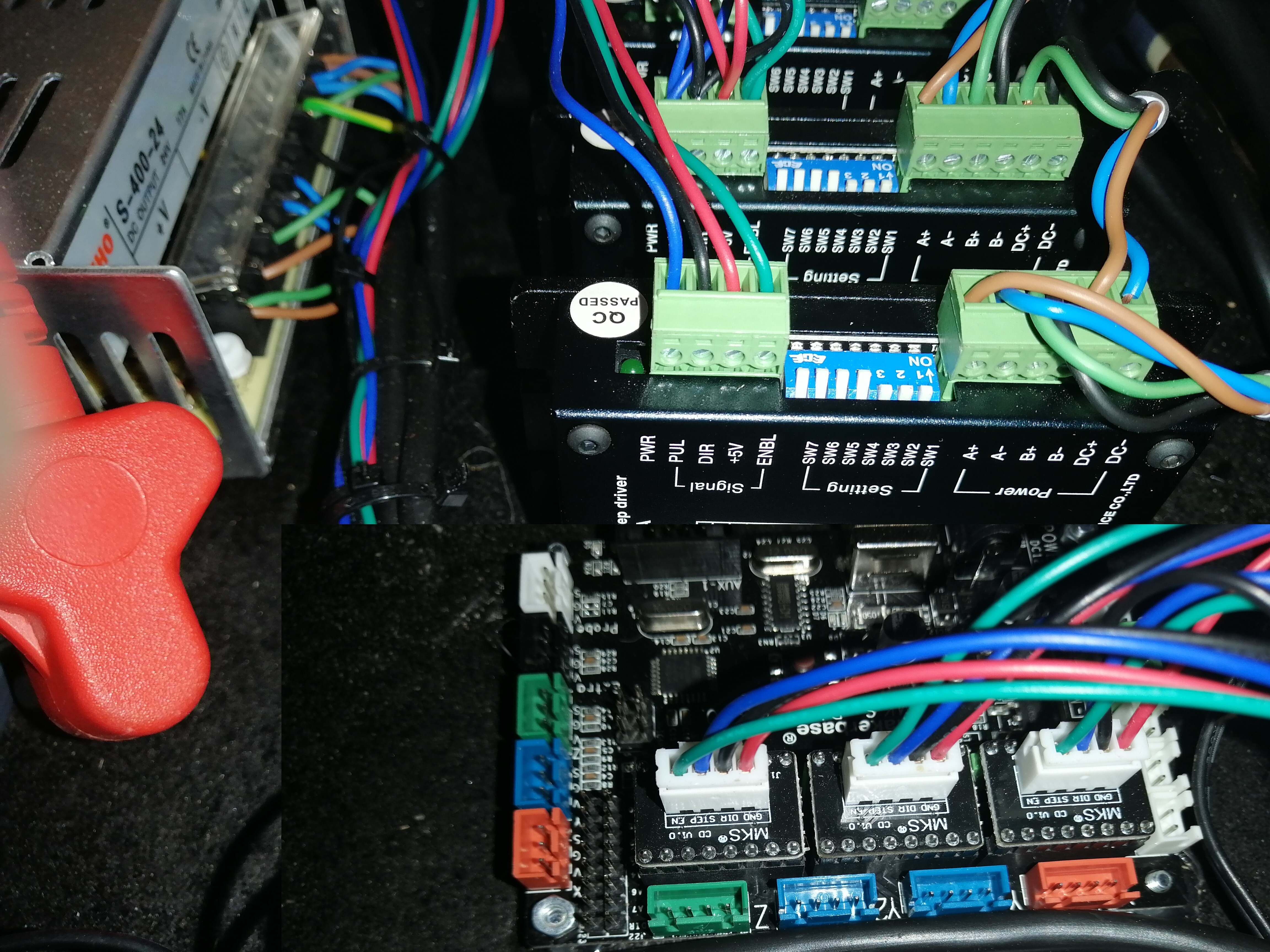
Apparently, you now have a new configuration. Please post pictures of your new wiring.
include pictures of the wiring for all axis:
Between the controller and the external drivers?
Between the drivers and their power source
Between the drivers and the motors
Where did you download GRBL from?
What instructions did you use to install it?
What are the operating symptoms you now see with this new configuration?
Unfortunately the suppliers are closed and only open tomorrow. According to the technician the DQ420MA is not working and I need to exchange them for MKS BT6600. I download the GRBL from GitHub. I tried all the advice. And nothing is happening. I do get the signals at the stepper drivers but it does not go through to the steppers. I do have holding torque on all the stepper motors but no command is been executed. I think is beter to exchange the drivers. As soon as I do the wiring I will sent you fotos.