Hey everybody, I bought several buck converters on Amazon (HiLetgo 3pcs XL4015 5A DC to DC CC CV Lithium Battery Step Down Charging Board Led Power Converter Charger Step Down Module) over a year ago they worked fine back then. I could adjust the voltage down from like 12V down to 3v for my ESP32 like I expected.
But now I’m trying to do the same and none of the 5 I bought work anymore! I even opened sealed bags to try new ones. I twist and twist the voltage and current screws till my fingers are sore and the output voltage remains equal to the input. I don’t understand what happened! Did they all go bad at the same time? All 5 of them are now faulty? I know you have to twist a lot, but over 50 revolutions with no change whatsoever?
I don’t have very much experience in electronics and these are my first buck converters.
I quadruple checked to make sure I was connecting positive red, to In +, and negative back to in -. Then I hooked up my meter to the out +/- to measure it. The red light comes on indicating it’s getting power. But what I measure coming out is exactly the same as my power source. I increase the volts and I see it increase in my meter as well. No matter how I twist the POTs nothing changes.
Aaah, I don’t. Maybe that’s the problem then. I wanted to measure the output first before hooking it up the ESP32. Do I give it a load then trim the pot down before I increase the input volts to 12? I don’t want to accidentally fry anything.
I have resistors I’d use, but if you don’t have any sitting around that doesn’t help. And I might simply be wrong. I’d wait for others here to chip in, my helpfulness is probably exhausted. But I’ve never seen this kind of failure case. I don’t know that I’ve used XL4015-based ones.
I hooked up a 9V motor and got it spinning while I measured the output voltage. Same result. I can increase/decrease the input voltage and the motor speed changes, but no matter how much I twist the pots, I can’t reduce it. This is crazy!
Thanks for your quick responses and for your suggestions! I’ll look into the XL4015 ones you mentioned!
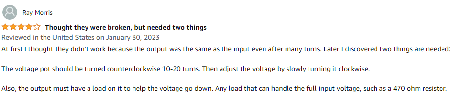
reading comments on an amazon product I noticed this:
All three boards I received tested good. As another purchaser mentioned, the terminals for POWER IN +/- and POWER OUT +/- are cheap and the screws are difficult to loosen. The potentiometers require many turns to make any changes to voltage or current, but this is desirable because it allows for minute adjustments. Ensure that voltage is adjusted BEFORE connecting a load to POWER OUT +/-, and current is adjusted AFTER connecting the load. Additionally, do NOT connect a load if the board is not powered because you risk damage to the circuitry.
That’s what you said you have, and I’m saying I don’t recall having experience with ones that use that chip. I’ve definitely used ones based on the LM2596. Doesn’t mean they are better, just that my experience might not apply.
Oh ok, that’s good to know. Since there is no upper/lower limit when I turn them I don’t know where it’s at. I’ve turned it probably over 50 turns one way and about that amount the other way to no avail. I tried the 9V motor but that didn’t help. I’ll try a resistor today to see if that makes a difference. Thanks!
if you listen closely then you might be able to hear the spring clicking inside the POT when you reach the end.
As you mention, it seems odd all of them would not work. If you own a DVM and know how to use it then you might be able to read a voltage across the POT and from one end to the wiper to see if there’s activity.
I didn’t know that, thanks! I’ll try listening to it next time. I do have a DVM and was using it to measure the OUT +/-, but I didn’t think to measure the pot. It’s totally encased in a plastic box, but I can see if I can access the soldered pins on the back of the board.
as a rule of thumb, that is how you look at these things. No need to open a resistor to measure its resistance, you work at its connectors. As for the POT, you know that it is fixed resistor(10k?) which you should be able to get something close across 2 of the 3 connections. The 3rd connector/wire/pin is the wiper and that moves from one end of the resistor to the other and back. So you should see that with one DVM lead on the wiper connector/pin and the other on one of the other two connector/pins. if you can’t see any changes in resistance as you turn the POT then you know something is wrong with the POT.
There are probably a few pictures on the Internet showing which pin is the wiper and which two are the ends of the fixed resistor.