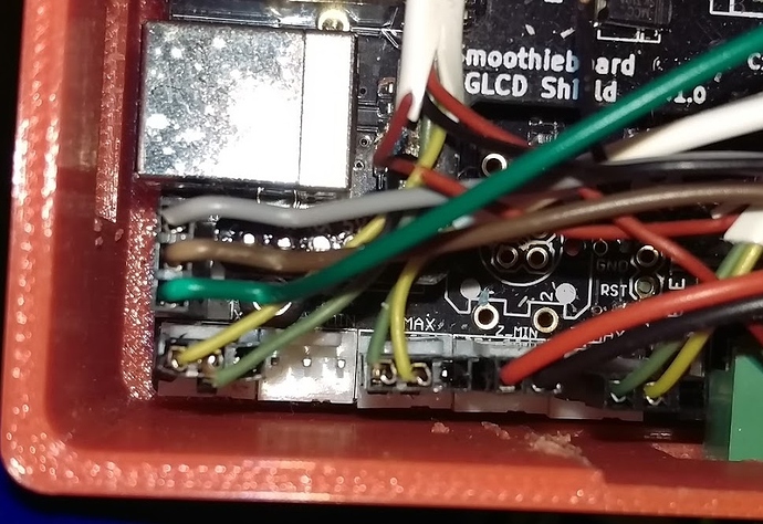
BLTOUCH …Hopefully this is what folks have been asking me for.
The photo attached will need my explanation just a tiny bit.
My Delta is five feet tall…so the wires changed colors on the way back to Smoothie.
Here is what makes BLTouch seem hard to figure out. The TWO and THREE pin connectors they supply need to be separated into a different group.
If you are not using MIN endstops, it does not matter which set of pins you use for signal from BLTouch back to Smoothie Servo module, so with that said…this is my color conversion chart…sorry
BLTouch WHITE wire to Smoothie RED wire in photo
BLTouch BLACK wire to Smoothie Black wire in photo
BLTouch ORANGE wire to Smoothie GREY in photo
BLTouch RED wire to Smoothie GREEN in photo
BLTouch BROWN wire to Smoothie BROWN in photo…(oops)
ZMin sees the BLTouch as a simple switch ( I think)
So ZMIN Pin 1.28 and GROUND right next to it are your switch terminals for SMOOTHIE input
I then went to XMin terminals to effect control and supply power to BLTouch.
Pin 1.24 is the switch output pin, so Smoothie communicates with BLTouch on that pin, (grey wire in picture)
Next to that is simply power and ground so BLTouch can self test and operate it’s tiny parts
Once you do all of this , M280 activates (rasies) the BLTouch pin
M281 deactivates (lowers) the BLTouch pin.
You have to add start and end scripts .
Start script for every print needs M280 as a single line
End Script for every print needs M281 as a single line
I know BLTouch tells you with PWM you can reset the BLTouch, but I have found that I am miles ahead to simply reboot the board, power reset performs the BLTouch self test and puts it in the proper state…and has been more reliable for me.
To each his own on that part.
I spent a few days trying BLTouch as a PWM device on Smoothie, and I may just not know how to make it work, but it was erratic at best. The day I made it digital in the servo module it worked perfectly
If you figured out my color conversion above, the next step is below
Do this to your servo module.
Switch module for servo control
switch.servo.enable true #
switch.servo.input_on_command M280 # M280 S7.5 would be midway
switch.servo.input_off_command M281 # same as M280 S0 0% duty cycle, effectively off
switch.servo.output_pin 1.24 # must be a PWM capable pin
switch.servo.output_type digital # H/W pwm output settable with S parameter in the input_on_comand
#switch.servo.pwm_period_ms 20 # set period to 20ms (50Hz) default is 50Hz
optional Z probe
gamma_min_endstop nc # normally 1.28. Change to nc to prevent conflict,
zprobe.enable true # set to true to enable a zprobe
zprobe.probe_pin 1.28 # pin probe is attached to if NC remove the !
zprobe.slow_feedrate 5 # mm/sec probe feed rate
zprobe.debounce_count 100 # set if noisy
zprobe.fast_feedrate 200 # move feedrate mm/sec
zprobe.probe_height 5 # how much above bed to start probe
associated with zprobe the leveling strategy to use
leveling-strategy.delta-calibration.enable true # basic delta calibration
leveling-strategy.delta-calibration.radius 120 # the probe radius
#the initial height above the bed we stop the intial move down after home to find the bed
#this should be a height that is enough that the probe will not hit the bed and is an offset from gamma_max (can be set to 0 if gamma_max takes into account the probe offset)
leveling-strategy.delta-calibration.initial_height 10 # height above bed to stop initial move
That is all I have, good luck, this works for me very well.
Don’t forget to M500 the settings after you run G32 on your delta !
BTW prints height is currently 607.49 mm with a one and a half inch heater assmbly, print diameter is set to 300 mm
