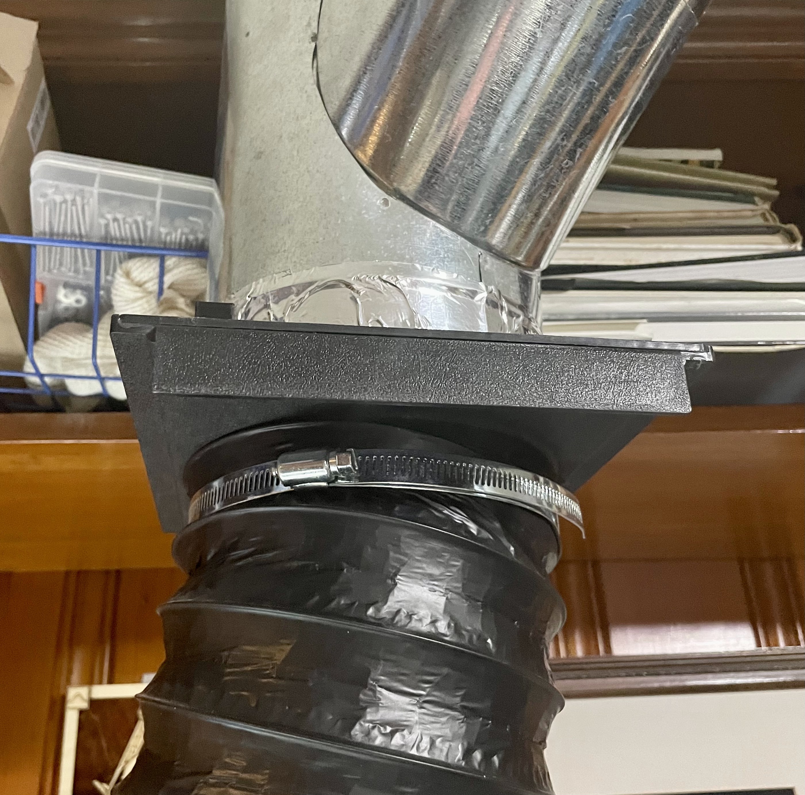
When I got my 50W laser I had to upgrade the exhaust to a 6in trunk and added a blast gate to allow me to also plumb in the K40. Also seals the 50W from outside air that may leak in. The blast gate is black and is overhead as my exhaust goes out through the roof. Because of this I can occasionally forget to open or forget to close the gate.
I’m more worried about forgetting to close it as the damper on the roof vent isn’t air tight and, during the summer, warm moist air can leak in and cause a condensation rain storm in the laser (which has happened once ![]() )
)
So I decided I wanted to added an easy to see, eye level, indicator for the position of the blast gate. Also wanted to keep it simple as possible. Settled on using a Red-Green bipolar LED and using a hall effect sensor to switch a DPDT relay to reverse the circuit polarity which then changes the LED color.
The video clip below shows the bread boarded circuit as I pass a magnet over the hall effect sensor.
Circuit and Materials
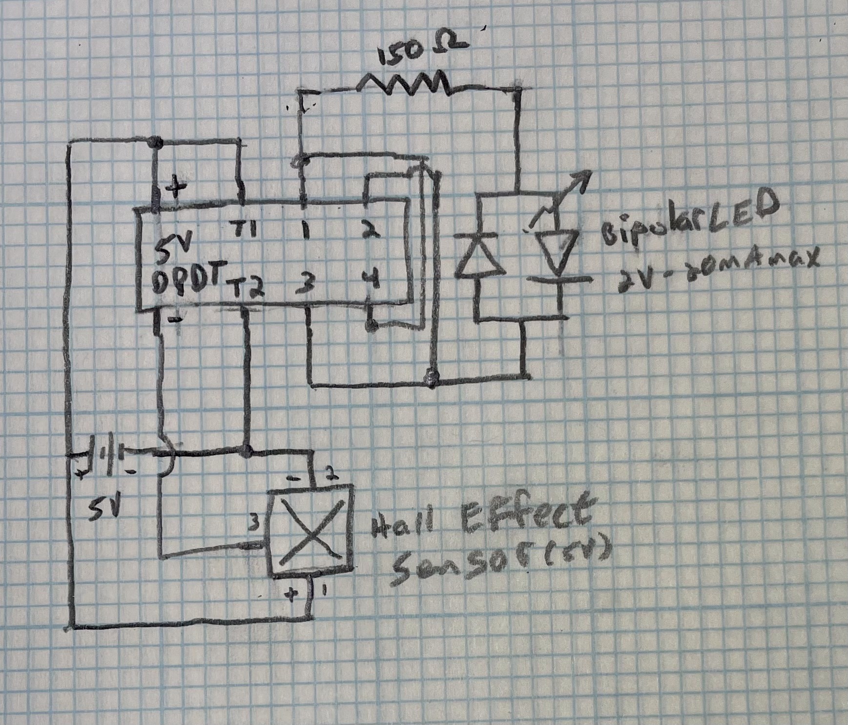
- Frosted 5mm Red-Green Bipolar LED 2V - 20mA max
- 5V Hall Effect Sensor (A3144)
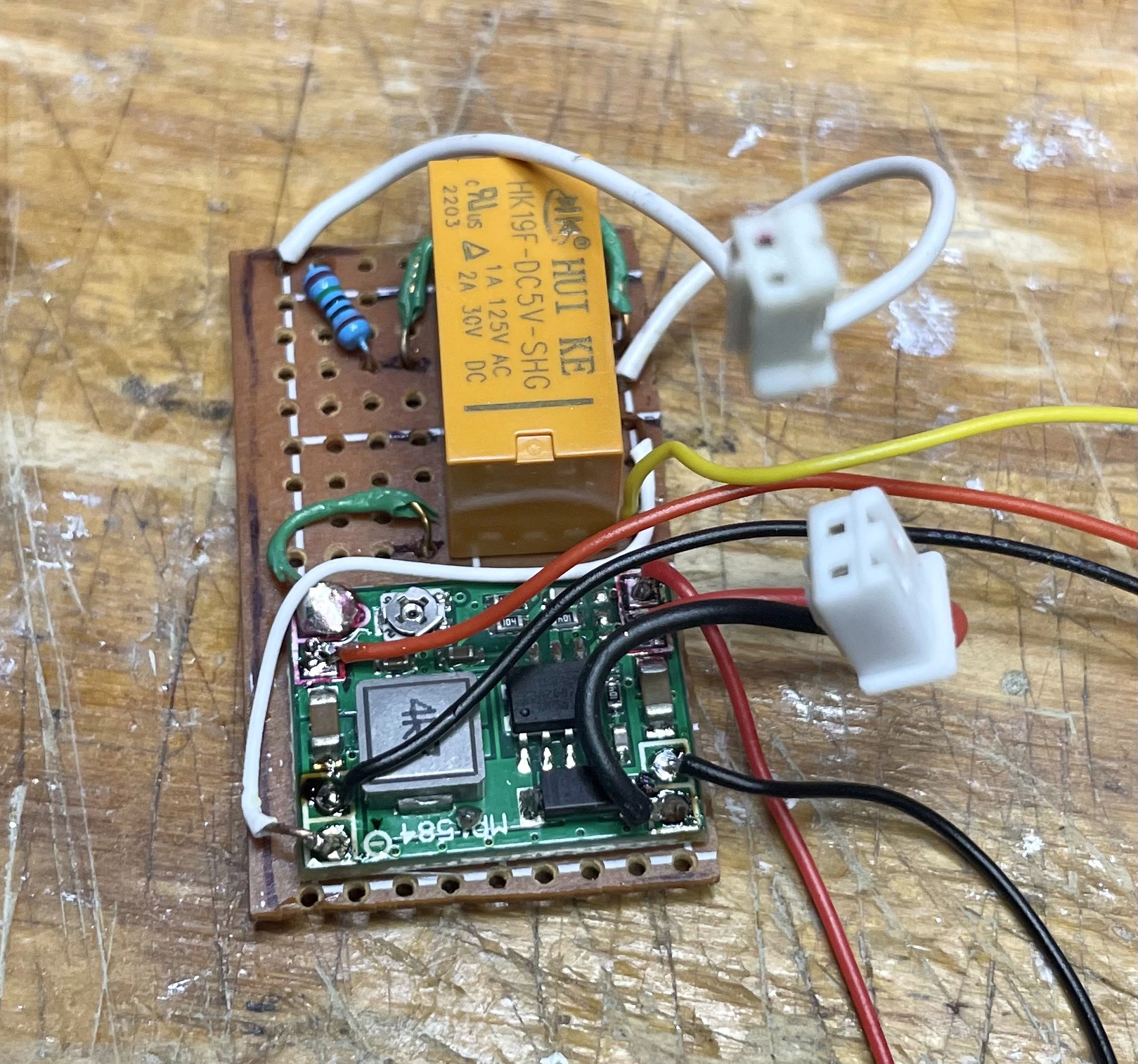
- 5V DPDT relay ( HK19F-8P-5V)
- 3 Conductor hookup wire
- Mini buck converter
- 150 ohm resistor
- Soldering board
- Appropriate size rare earth magnets to embed in the gate (Mag thickness equal to or less than the gate)
- 3 pin and 2 pin connectors.
Layout
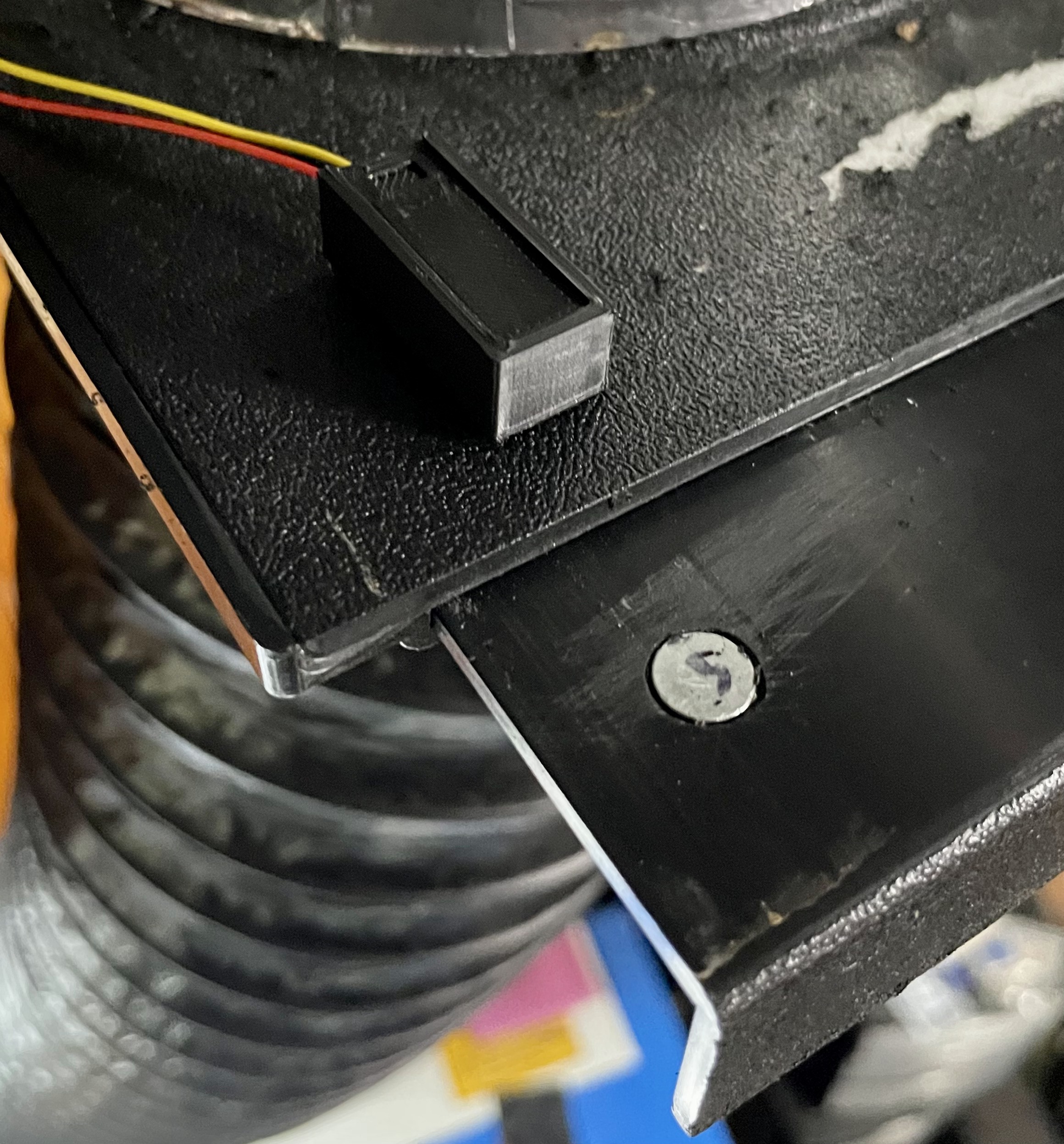
The hall effect senor was mounted on top of the blast gate housing and a magnet was embedded in the sliding gate at the same position as the sensor. The rest of the circuit was housed in the thermometer housing that I had 3D printed before that sets on top of the laser with the LED on top of that.
I 3D printed a housing for the sensor. This isn’t really necessary as you could just hot glue the sensor in place. The sensor was mount to a piece of solder board and hot glued in place.
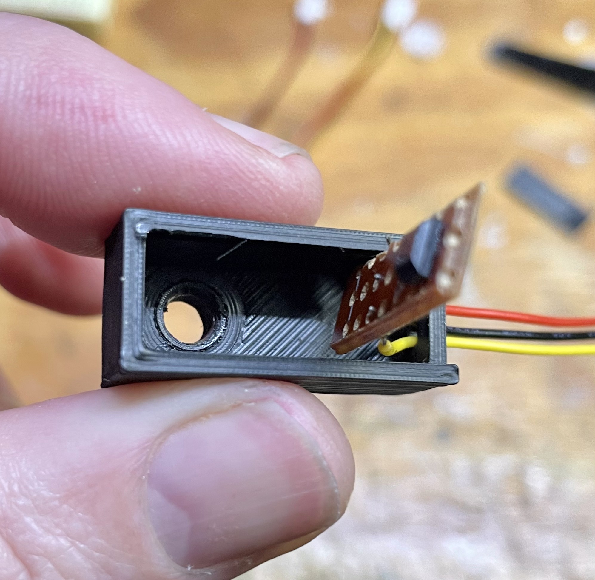
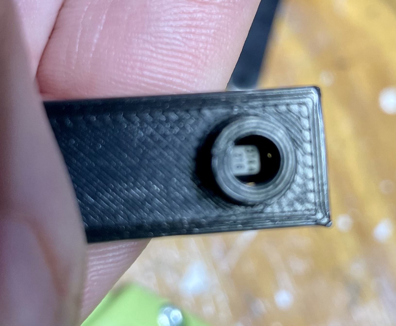

Drilled a 8mm hole in through the top of the gate housing and into the gate. Opened the gate and finished drilling the hole. Mounted the sensor housing to the gate housing in the drilled hole. I used two 1.5 x 8mm rare earth magnets, stacked together, to embed in the 3mm thick gate. Had previously determined the correct orientation of the magnet.
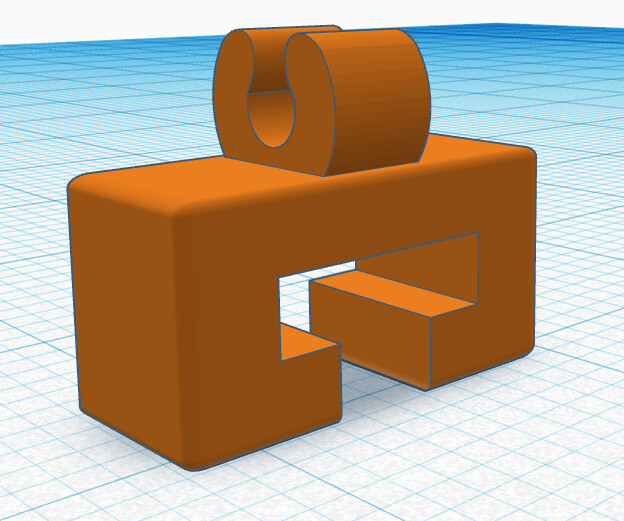
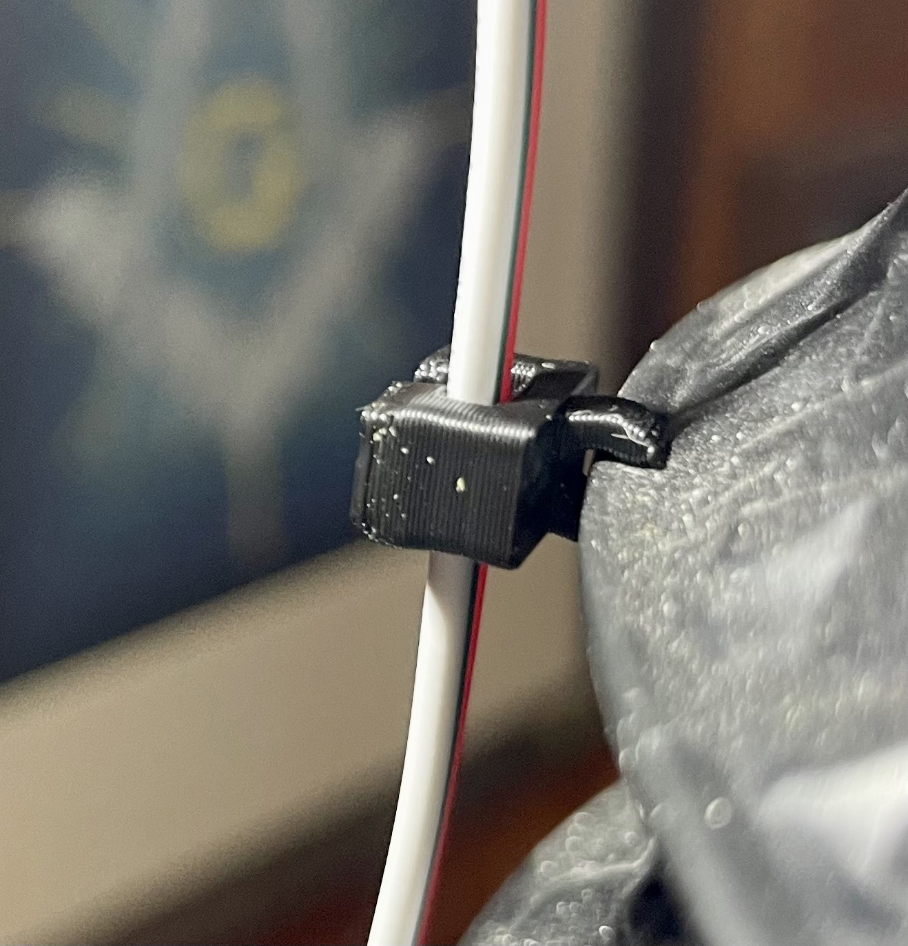
Rather than just let the 3 conductor wire hand down, I designed and 3D printed some wire clips that clip to the wire support of the flex ducting. These work really well and allowed me to cleanly route the wire down the ducting
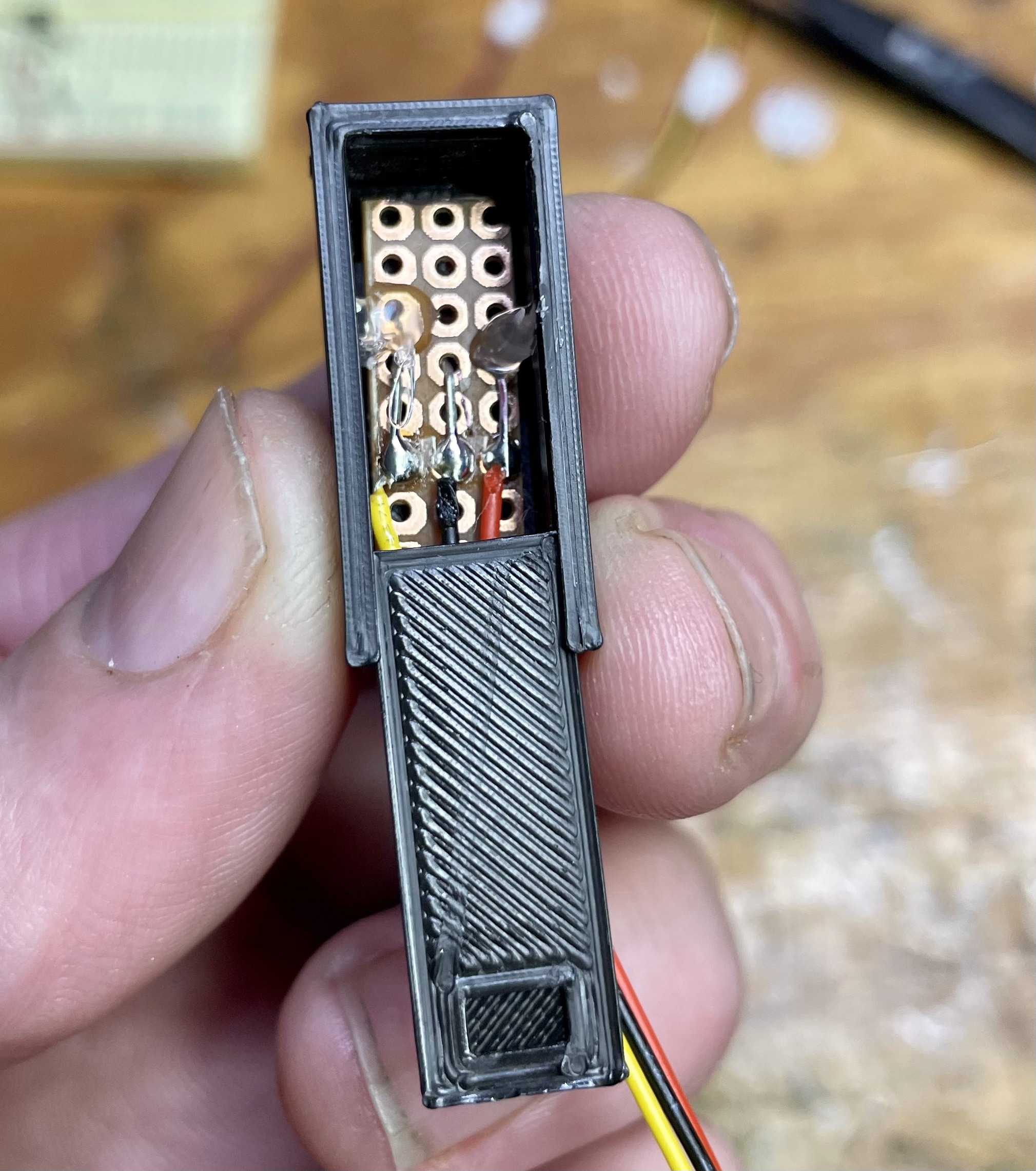
I already had 24V from the LPS running into the thermometer housing so I used a mini buck converter to step down the voltage to 5V to run the circuit. Cut a piece of solder board to fit in the bottom of the thermometer housing and wired everything up. Made liberal use of wire pin connectors to make it as modular as possible.
Dilled holes for the legs of the LED in the top which clip into a female pin connector.
Everything just managed to fit in the housing so I didn’t need to reprint it. ![]()

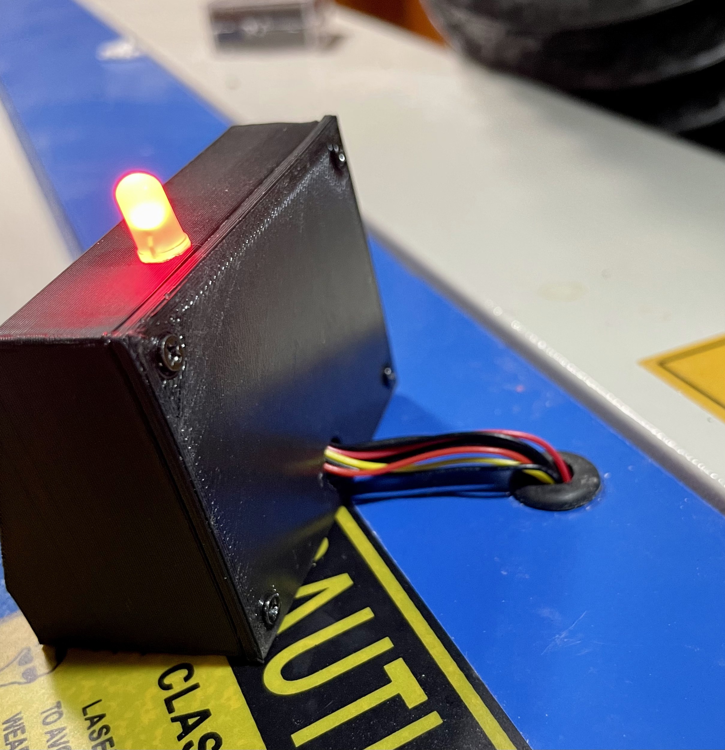
And… ![]() …it works!
…it works!