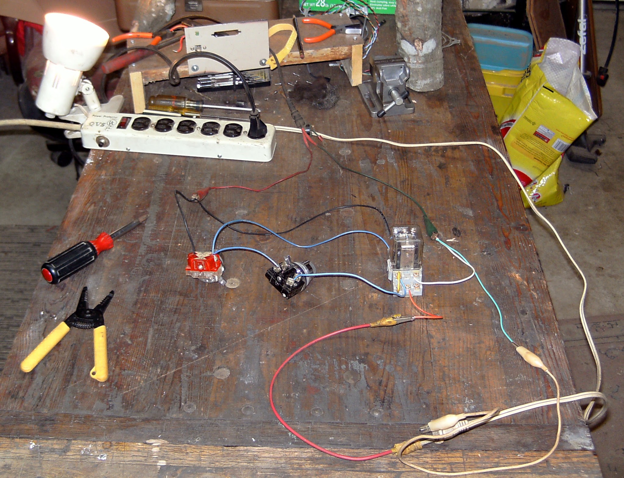
Bench testing my latched relay start stop button circuit. Just to make sure it works, before I build it into my new control panel. And it does.
It’s a long story why I need to include this. Which basically boils down to practical placement issues with the control box, and the panel. I wanted to put the panel right on the box, but it isn’t going to work out that way.
So this fixes that for me. The relay will switch power coming out of the PSU to the rest of my electronics. Yeah I could have just run a wire up from the PSU to a switch, then another one back down again. But that’s majorly crappy.
Ice cube relays and industrial momentary switches are much cooler. Plus I had it all lying around here.
Added the same to some machines at work recently.
@Gee_Willikers yeah I want the controls where it is convenient for me. The relay keeps PSU lead length a reasonable distance while putting them there too.
Paul, I’m partially following your setup, but can you specify what the red and black components are? Have a wiring diagram?
missing/deleted image from Google+
@marmil
the red and black components are the momentary push buttons. The red one is stop, and it is normally closed. The black one is start and it is normally open. I’m using the common latching relay setup here too. I’ll find a schematic of it.
This is not precisely what I am doing, but the broad strokes are right http://sound.whsites.net/articles/relays-f12.gif
When you press the On button that energizes the relay, and then the relay energizes itself, or stays “latched”, until the Off button is depressed, that cuts power to the relay, and turns it off.
Sometimes this circuit is called a magnetic switch.
I even have a switch ahead of all of this like the “Safety Interlock” on that schematic (which isn’t in my bench lash up). But my switch powers on the PSU along with allowing the Start and Stop buttons to function.
The second contacts of my relay control the PSU power out to my electronics. My BOB, and motor drives.
I haven’t inked my plate yet (I’m probably not going to either), but I’ll try to take a picture of it now. Meh, it is a little blurry http://i.imgur.com/P5rh5An.jpg just a quick sketch really.
Appreciate the info and I understand it now. Thank you for the images.
@marmil
you’re welcome. As they say, a picture is worth a thousand words. They might have low balled that estimate too? The magnetic contactor circuit is a handy one.