Being unable to work out how to embed a picture in an existing discussion, I took the easy way out…
Here is a first-draft of an MDF Eustathios. I haven’t worked out what all the holes are for, so I have put them in anyway. I suspect most of them aren’t needed in the way I have got them and I can rationalise that down to some screw posts, etc.
Since this first draft, I have looked more at the models and am confident I can mill the sliding components and the z-axis gantry. I will just need to make a couple of parts and assemble them for the more complex 3D items. My CNC is set up for flat sheets, not 3D milling, but using 2.5D techniques and lots of glue and clamps, I am confident it is do-able.
So far I have concentrated on the mechanical side - I haven’t really looked at the cabinet, but I think there is definitely room for improvement there - at the moment it is just a box with tabs and a few screws to lock it together.
Looks great. Just be cautious of weight for any aluminium parts. Heavy parts, High speeds and high acceleration will easily overcome stepper holding torque. I’d use nema 21s or high torque 17s if you have them already for cnc machines :).
I wasn’t going to use any aluminium - all MDF and glue. Treating MDF with cyanoacrylate makes it amazingly tough, which is what I would do around screw holes, etc.
I have a ton of very shiny CF rods as well that I am thinking of putting on test as smooth shafts. I have some that take an 8mm linear bearing, but those bearings have sharp little runners - I suspect they would just eat up the surface of the CF acrylic.
ABS is .038 lb/cu in. (sorry for the ancient measuring schema) and MDF - the stuff I use made from tropical hardwood - is .037 lb/cu in - so almost identical. But… a lot of air in printed parts and there won’t be much in my milled MDF.
As it’s an exact dimensional copy of the sketchup model posted on here, including using its x-y gantry, but made in 6mm mdf (by taking the plastic components, slicing them into 6mm bits and assembling) I am unsure why it resembles an h-bot or makerbot - unless the eustathios is a copy of those?
After doing some digging in my deformable materials notes, I’m tempted to try teflon extruded bar stock as the z-axis bearing. It is easy to fit into a piece of routed MDF and allows for really close tolerances when you face the MDF with some kind of melamine veneer, compared to accommodating a linear bearing and rod. I could almost make the entire interior dimension a sliding plate, and at the price, it’s cheap to put in 4 sliding bearing surfaces. With 16mm x 4mm bar at $15/kg, it is significantly cheaper than comparable smooth rod and bearings. The amount of melamine is paltry and my wood supplier is also the local veneer supplier - he probably has a metre off-cut I could skive off him…
I’ve used PTFE for table-saw and router sleds, but not for a printer - I don’t see why it won’t work and the sliding coefficient is less than double that of a linear ball bearing.
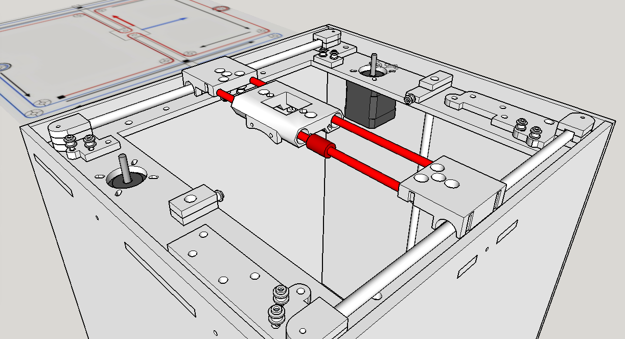
@D_Rob it’s the slid3r mechanism. The red/blue lines at the back of the image are the ones I drew up about a year ago to explain the mechanism.
Incidentally @Mike_Thornbury , the ‘blue’ axis could be used for z stage. With one instance on oposing sides of the machine: that would then give 4 corner support for the bed. I’ve been meaning to try it but too busy atm.
Thanks @Richard_Horne It was quick and dirty, but having your originals was what made it accurate.
You can tell me, what are all the additional holes for? I see the one in front of the pair of pulleys is for the spectra anchor for one of the circuits, but there’s a lot of other holes I can’t see a reason for - except for electrical feed for the hotend.
@Mike_Thornbury Any spare holes you see are for routing the end-stop cables or wiring mounts etc. they do not have any specific reasons for being scattered around the machine, I just added some in the design so I could secure and route various cables.
The ‘spare’ holes on the X/Y carriage parts were to allow a single part to be printed, it’s identical, but at each end different mounting holes need to be used for the spectra line and bearing position.
After some quick tests, I only actually printed one single set of the main components, and a few minor revisions for fit, it all just worked. If I ever update the design I will spend a little more time on the industrial design aspect and optimization of parts and fastenings.
@Mike_Thornbury ‘special’ tensioning system consists of the ends of the spectra line being wound around an M4 mounted bolt - see the images on Youmagine / my blog. You should run the machine for a while and then re-tighten around the M4 bolts+washers+nut. When tight the lines should twang.
I was thinking about a spring tensioner, but I don’t think it can achieve the required amount of tension. I’ve been reviewing old HP inkjet and scanner schematics to see how they did it. I should have paid better attention when I had them stripped down. Of course the new ones are all belt-drive, but the scanners all used to be line.