He did. That’s in the OP. (And to receive direct help from Cohesion3D, just post in their forum and their support team will be happy to assist you.)
When you screw the screws in, they push the stage that holds the mirror. The screws are technically called “stage maintenance screws” and are very fine pitched to give you fine control. You can download STEP files for various laser optics sets from grabcad. They are fundamentally quite similar, and you can load up STEP files in FreeCAD or most any proprietary CAD to get more of a sense how they work. Three points determine a plane; the three screws set the mirror plane.
I got the mirroring part of the problem figured out. Looks like my origin is top right (don’t know what determines that or why).
New problems and I don’t know if this is a laser issue or a lightburn / cohesion board issue, so I will be posting on those forums too:
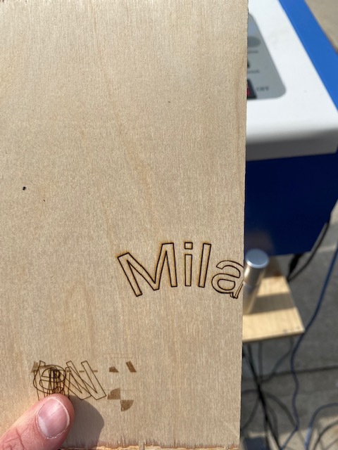
When I start a job sometimes the machine randomly goes to a completely different location. For example, I wanted to do some test burns for a dog tag I would like to make my new puppy. I ran the word MILA in the middle of my work space. The K40 goes to the bottom right and writes MILA with all the letters on top of one another (See first photo below). Without adjusting anything, I hit the start button again. This time the K40 goes to the top right and spells MILA out properly. I made no adjustments, I didn’t touch the program or the work piece.
I have coordinates set to absolute. Why is it randomly going where ever it wants?
Same thing when I went to do a dog tag, I did it on the wood first in one spot to give me a reference point. Slid a dog tag over top of the wood in the same spot, the k40 decides it wants to go somewhere else entirely. I can’t reliably fire my laser in the same spot to do repeat jobs.
I try and do the calibrate camera alignment in lightburn. It gives me a grid it wants burned into a piece of wood, similar to above, the laser tries to burn it in a different area every time I try to run it. A lot of the time it tries to run half of the grid right off of where my gantry is. When I look at the file, it is dead center set to my machine
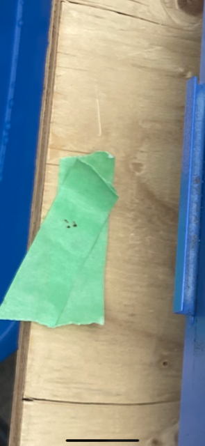
I was doing my laser alignment. I think I have it setup pretty good for the most part but I want to tweak things a bit more after running a few more tests at the end of today. I am seeing 3 dots come from my laser tube to the first mirror at every push of the button. Am I in TEM-01? with a dying laser? I tried doing 3 passes at 10ma and 20mm/s and I am only scratching the surface of 5mm plywood. It burns in images, but nothing crazy and I can’t see this cutting anything. I also am not ruling out it being a focusing issue.
The guy I bought it from included a new laser tube, so I am thinking it may have been on its way out…
Without a picture of the dots it is hard to speculate exactly which mode, but unlikely to be in TEM00 any more. So yes, tubes don’t spontaneously return to TEM00; it’s on its way out.
If it is pooched that is fine, I will have to google how to install the next one. My only issue is I am moving in about 1.5 months and I would of rather installed the new laser after I get to the new place and the thing won’t get bounced around any…
See the K40 Intro linked from the top of the page. That category includes tube replacement info. In particular, the hard part of replacing a tube is splicing the high voltage cable.
I think the shot you posted for the ‘size and positioning’ area is not doing what you think. Here’s the windows of Lightburn. Here’s the documentation on that area.
Don’t know if this helps, but in Lightburn you need to go to edit->device settings and set the ‘origin’ to where you device homes on power up. This isn’t very clear, it’s one of the four corners. From what I understand of a K40 it’s the back left (top left,) same as mine.
Thanks, I thought this too, but it seems to mirror how the machine spits out my work when I set it that way.
I will look at it again, are the homing switches big red squares? Is there any way to edit where these are or would reversed wires causes these to make the machine act opposite of the way it should?
Mcdanlj is it confirmed my tube is no longer any good?
This comment “but it seems to mirror how the machine spits out my work when I set it that way” assures me it’s a configuration issue. Been there, done that… One of the parts your data is flowing through is referencing a different ‘home’ or absolute 0,0 position. If it’s only Lightburn and your laser, one of them is mis configured. Don’t need to know about switches, it’s where the head homes. On power up it ‘heads’ (both x and y) to the limit switches. This is in the configuration of a ‘homing’ direction on the controller.
When you power up your machine, it will ‘home.’ Pick that corner. BACKUP you original configuration before modifying ANYTHING. If it’s not too late.
The machine defaults to certain positions, setup by the manufacturer for it to operate with accompanied software. The software has to be configurable to take into account where the home position is, or absolute coordinates of 0,0. Don’t try and modify the internals until you get the ‘hang’ of what you’re doing. You’ll just drive yourself nuts.
I have always found that when some kinds of image reversals or something similar happen, it’s a configuration issue. If you haven’t modified the machine or it’s firmware, the software must be the culprit. That’s a good starting place.
Another thing I found, thinking something works one way when it doesn’t. If possible read the documentation. All of the ‘buttons’ and ‘check boxes’ are in the documentation for lightburn.
Mike, can you verify that the corner you picked in your Edit->Device Settings->Origin is the same corner you picked when you created your machine device type AND it’s a good idea to have the Auto-home on startup option turned on too. They should show the same as they are probably associated but good to check and making sure the machine goes to Home position when the controller powers up and when LightBurn connects is a good idea. Because if the home position is not consistent then designs will not show up where you or the software expects them to be.
There are both a Home position and Origin elements to deal with but I keep them the same most of the time. ie on my K40/Smoothieware the home position is top/left and my Origin is set to Absolute Coords so I see the little green dot/box in the top/left and the little red dot/box in the same corner.
If I set the Origin to User Origin type with the center radio button selected then you’d see the origin green dot move to the center of your work area. You can also set user defined origins with Set Origin and Clear Origin buttons and I will do that sometimes when I’m repeating an etch. For example I cut out Xmas bulbs and had a stack of blanks, I place a template on my work area with magnets and set the origin to the center of the bulb. Then I change to Current Position type of origin. Now when I hit GoTo Origin it will always go to the center of the bulb and my design will start burning there.
ok, I did some more reading and it sounds like I put the wrong smoothie ware onto my cohesion mini board.
So, I have decided to go back to GRBL-LPC as that is what was working. I downloaded the new v1.1 version here: grbl-lpc C3D Mini Firmware Builds – Jim's Embeddedtronics I took the 4 axis bin as I am thinking that is what I needed?
Flash it in, fire up the machine and it won’t home in lightburn. I get the alarm 8 Homing fail. Cycle failed to clear limit switch when pulling off. Try increasing pull-off setting or check wiring.
Now, when I had smoothie in it would move around when I asked it to go home, so I know the wiring is fine.
Does anyone have a config file for GRBL-LPC for the K40? my bet at this point is I have a bunch of settings off…
Why 4 axis? The K40 only has X and Y axis. Since you installed firmware for 4 axis it is probably looking for homing switches for the non-existent axises.
Because I am having a hard time finding information and I can’t get any responses on the C3d board so far.
That link you sent seems to talk about smoothieboard software and I am not sure if the nano board is the mini board.
At this point I know laser GRBL was what was on there when I bought it from the guy and I just want to go back to what it had and try and work from there. Ive probably spent 30+ hours trying to figure out firmware stuff, I just want to start using my laser. I am confused and frustrated at this point
you need to get it to home correctly and only then would I even start trying to move around the bed. MAYBE I would move 5mm and see if it moves in the right direction and by the correct amount so I know my steps/mm are correct and my motors are wired correctly. But you have to get it to home and trigger the 2 limit switches.
What software are you using to control you laser? Often the software will put labels on those settings you listed so you know where to look. I’m going to post one of my ocnfig files for a GRBL laser just so you see the comments and can understand what those numbers you have in your machine mean and maybe if they are correct.
Sorry, I forgot that Ray at Cohesion has been out at MRRF show and not responding to forum posts. I saw he just started responding last night. I don’t have GRBL-LPC on my K40 so I can’t share a config file but I do have a smoothieware bin file and config.txt file if/when you want to try that.
But many of us have GRBL based machines too so we can probably get you running again but it will take more time since as was pointed out, GRBL is configured with $ commands and some of them are instructions to save to flash.
I am game to try anything at this point. If you want to email them to me that would be great. I think I just sent you a PM.
Mcdanlj I just tried putting $5-1 and it smashes the laser into the top of the machine and then shakes going left to right. It eventually hits the switch and then throws an alarm 9
ALARM:9
Homing fail. Could not find limit switch within search distance. Defined as 1.5 * max_travel on search and 5 * pulloff on locate phases.

 Take care…
 One of the parts your data is flowing through is referencing a different ‘home’ or absolute 0,0 position. If it’s only Lightburn and your laser, one of them is mis configured. Don’t need to know about switches, it’s where the head homes. On power up it ‘heads’ (both x and y) to the limit switches. This is in the configuration of a ‘homing’ direction on the controller.