Bcnc is mostly a ‘GCode Sender’ and that means it’s primary function is to send GCode files, as a stream of lines in the GCode text files, to the controller at the other end of the “wire”(USB, RS232, wireless, etc ). So yes, you have to tell Bcnc a bit about your machine size but that’s mostly it.
Some other software generates the GCode files and that is generally called the CAM software. The CAM software is where you load up some design( DXF, STL, SVG, etc ) and in that software you also tell it a little bit about your preferred origin, maybe the work area max size, etc. You also tell it what controller will be receiving the GCode so it can generate the correct syntax of GCode since some differences like what’s the standard spindle speed command format, special “M” codes etc.
Once you have your design saved as GCode files( also called toolpaths in CNC industry ) you use a GCode Sender like Bcnc to load the GCode and sometimes render a display showing the design. You might use it to set your origin X, Y and Z and a few other things but it’s main task is to send those GCode commands down to your controller / machine to create the desired product.
Given the pictures you are showing I don’t think you are understanding what it means to send the command “G0 X100” to the controller otherwise there would have been some proof you did this in the pictures.
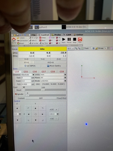
Do you see the little text box at the bottom left of your Bcnc windows where it says “Command:” next to it? There is where you type in “G0 X100”. note: do use capital letters and don’t seen the quotation marks.
I don’t know why you keep putting and “X” in front of things which are not supposed to have it but please take your time and post correct responses. $100 is not the same as X100 and since we’re not playing horseshoes, ‘close enough’ does not count and yes it does matter if we are to understand what you are doing and why things are not working as you expect them to be working.
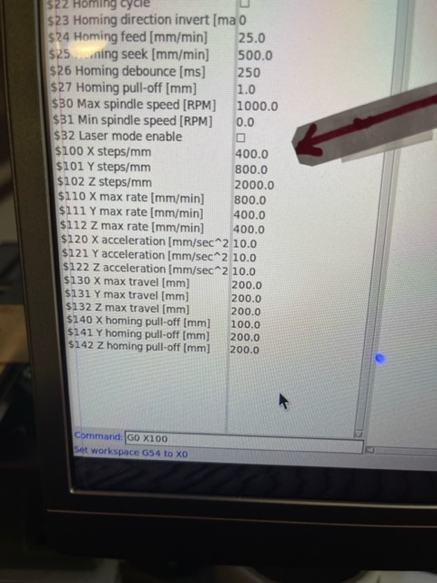
The DM542 stepper driver dip-switches set steps/rev for 1.8° motors (which you use), so your calculation would just be: 2000 steps/rev / 5 mm/rev = 400 steps/mm
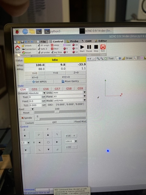
So set $100…$102 to 400 and check if a 100mm move (G0 X100) realy moves 100mm
]]
Great, so now you know what setting for Steps/mm to use for all of your axis which use those same screws and stepper motor settings. Like maybe your Y axis?
See if increasing your X max rate helps improve movement using:
$110=2500.000
For What It’s Worth( FWIW ) I found a guy who has a 3040t-CNC who put GRBL on an Arduino Uno and used TB6600 drivers and NEMA 34 steppers. He had these settings for GRBL: Notice he also is using 400 steps/mm
WHY are you changing the steps/mm( $100 ) when you said it moved 100mm after giving it the command to move 100mm( G0 X100 ) with a setting of 400 steps/mm? WHY NOW 350? This makes no sense.
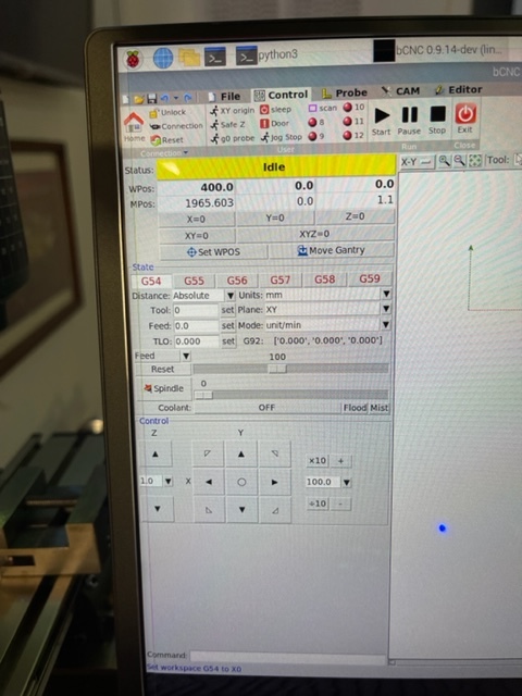
You can not have it both ways… If you set $100 to 400 steps/mm and it moves 100mm when you command it to move 100mm( G0 X100 ) then the setting is correct. If you set your X origin to the farthest to left it can go( X0 ) and then command it to go 400( G0 X400 ) and it hits the other end before reaching 400mm then your working space is not 400mm and you have to figure out why. You don’t get to change $100 to something smaller than 400 steps/mm just so you think it moved 400mm because the display says it has moved 400mm.