Am I not seeing something?
Using the LightBurn software.
Both the software and hardware have a 400mm x 410mm grid. The way the unit is assembled the laser beam cannot travel down the y axis farther than the 340mm mark on the rail. Seems like the only solutions would be to a) relocate the y axis to the other side, but would require drilling and tapping for the stop, or b) relocating the laser unit to the other side of the x axis beam. That doesn’t look too hard and seems like the most obvious solution.
As it is right now it works just fine, but the mm markings on the software grid don’t coincide with the markings on the rail. It APPEARS that they would if the laser was on the inside of the x axis rail.
What is stopping it from travelling the full depth of the Y axis? Looking at the product page, the Y carriages have 2 wider standing wheels on the top and 2 closer wheels on the bottom and the Y axis rail slots go from front to back but the numbers are inboard of the ends so it should be travelling the full distance of the markings.
How about posting some pictures showing it at both ends of the Y axis?
The orientation I’m using is that the rail with the Atomstack name is the rear and the front rail has the yellow warning label. The traveling carriage (with the laser attached) is the X axis, and yes, it does have full travel. Problem is with the Y axis travel.
The Y axis side rail (with markings) has the 400mm marking close to the end rail (with the Atomstack name). With the laser located on the front side of the X axis member there is physically no way the laser could reach the 400mm mark. As far as it will travel up the Y axis it about the 350mm mark. After that it hits the stop pin. IF the X axis component was reversed, or the laser unit was relocated to the other side of the rail the laser beam would be able to travel the entire 400mm.
Oh boy: I am a “NEW USER”, therefore incapable of uploading images.
Another problem the current configuration causes is the HOME position. HOME places the laser adjusting screw right over the front rail
Doug: if you can give me an email I’ll send you the picture. tom.lea17@gmail.com
You should use the orientation the manufacturer designed into the machine and even more so if you are new to the machine or the field of laser engraving.
Next, go back to the assembly instructions and verify you assembled the machine properly. Pay close attention to the orientation of the X axis relative to the front and back of the machine(as designed by the manufacturer).
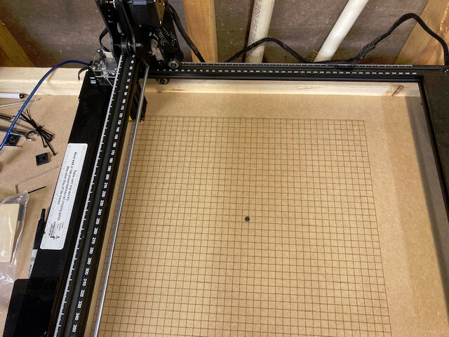
OK Here’s the picture. As far as I can see the frame is assembled according to all the info provided. I actually printed off the grid from Ligntburn on a piece of MDF.
Now, if you look at the 400mm marking on the side rail and the closeness to the back rail (with the Atomstack name) there is no physical way the laser beam can get to the 400mm marking. It would have to be on the other side of the X axis traveling member.
On another note, the end line on the grid was selected on the software to be at 400mm. It actually printed at 350mm according to the markings on the side rail.
I’ve even considered swapping the side rails and starting with a different home position. Don’t remember what the downside of that was.
Hope this picture works.
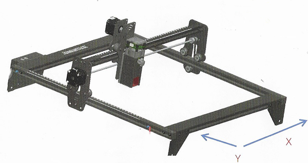
This is the assembled item picture from the user manual. Given the orientation of the laser on the x axis traveler, I still fail to see how the laser beam could ever get to the 400mm mark. There’s physically no room to do it. The traveler wheels would contact the stop pin long before that.
Thanks
Tom
The image helps but is so low resolution I can’t see the numbers and there is no “AtomicStack” label in sight so it’s difficult to tell which is the front or the back. If that white sticker is the “AtomicStack” label then the X axis is installed backwards because in the manufacturers drawing the Atomic Stack name is at the REAR of the machine and the laser diode head is mounted on the side away from the AtomicStack label.
What I can see from the manufacturers picture is that the laser is forward of the X axis beam and the stop pin in the direction of that offset is so the laser beam doesn’t hit the wide plate which is the front of the frame. It also appears, in the manufacturers drawing, that the number label along the Y axis does not line up with the laser beam location but instead some location on the carriage. So my questions now are:
Does the laser mark along the X axis very close to that front plate and if not can the stop pin be moved to allow a closer marking position without the laser head contacting the front plate?
When you make a mark along the X axis at the very front and then moved to the very back and mark again, what is the measurement between these marks? Please don’t tell me what’s on the side rail, actually measure the distance between the marks. You may need to increase the size specified in the firmware and in LightBurn to allow marking to the largest possible Y axis distance.
IIRC that would be GRBL setting $131 and your Y axis setting in LightBurn is in the device setting.
Thanks for the response. I appreciate it.
The grid I printed was taken from the Lightburn grid. The printed lines are exactly (by caliper) 1 CM apart.
Also: cannot move the stop pin.
As for the printed grid lines and the markings on the rail, they DO line up, but are 50mm off. The Zero mark on the rail lines up with the 50mm line and the 350mm mark on the rail lines up with the 400mm printed line.
The vertical lines ( X axis) line up perfectly with the printed lines on the grid. I wouldn’t think the X axis traveler would be mounted backwards because the 0mm mark on the X axis and 0mm mark on the Y axis will line up (manually) to form the 0 - 0 corner of the grid. If I reversed it, the 410mm X axis and the 0 y axis would be the grid corner.
Yes, the diode head is on the opposite side of the X axis traveler from the AtomStack label.
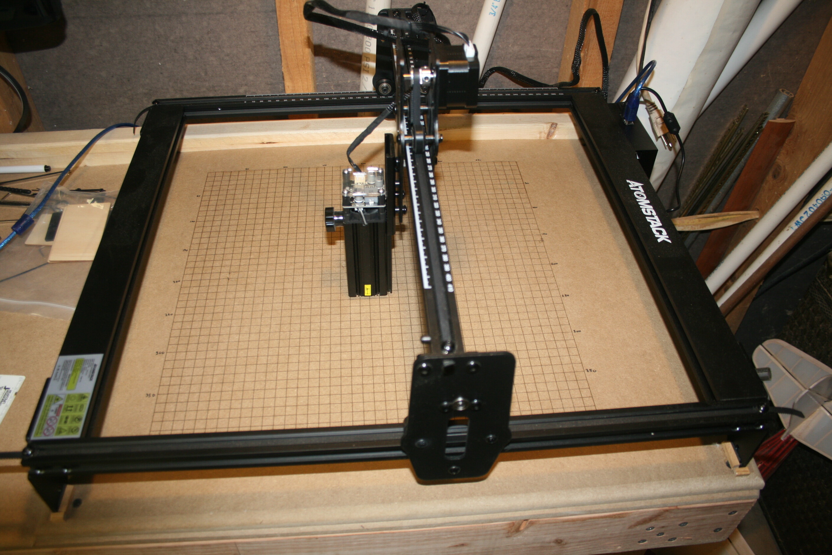
Here’s another pic of mine. It’s assembled exactly as the instructions and photos show.
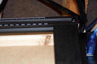
On the last note: here’s a pic of the Y axis scale. The 400mm marking ends 1.5cm from the back rail (with AtomStack name). With the laser head on the opposite side of the X axis traveler how would it be possible to ever print anything in the last 50mm of Y axis travel. The x axis traveler contacts the rear stop
when the carriage gets to the 350mm marking.
Good news is that I DO have the travel on both the X and Y axis to print and use the full grid. I have marked the printed lines with the correct measurements and I have to use the left rear position for HOME. If I use front left I cannot get to the “blossom” knob.
Thanks again for your help.
Tom
Tom, you’ll want to not use the word “print” when you are talking about the laser machine marking something. It’s very confusing since it is not “printing”(additive operation) anything, it is engraving or cutting or burning or etching. I had thought you used a printer and created the grid on some cardboard or paper and didn’t use the machine to engrave the grid. I know you said LightBurn but figured you exported the grid design and “printed” it.
As for the capabilities of the machine, I saw it mentioned that this machine has a 30cm x 30cm working area. I personally would not have purchased the machine without clarification from the manufacturer regarding the working area. They go out of their way to NOT tell you the working area in their documentation. They even only state the RULER MARKING sizes… https://www.atomstack.shop/products/atomstack-a5-m40/
So figure out what the real/usable maximum X and Y distances are, set your firmware up with those numbers($130/$131) and setup LIghtBurn with those numbers and use the thing.