Anyone have any guidance on how to setup a roller style rotary using the A axis? Previously I had swapped the Y axis control to the the roller with good success calculating the the steps per mm based on the circumference of the roller. I would then size the image to be engraved relative to the diameter of the part being processed.
Right now I am using 200 steps per rev with 1/16 microstepping. The rollers are 35.6 mm in diameter. (20016)/(35.63.14 roller circumference) = 28.87 steps per mm. This is the value I send to GRBL.
When creating an operation in LaserWeb, I set the A diameter to 50mm and the engrave pattern is a 10mm tall piece of art. The issue is that the resulting G code and etched the pattern end up being closer to 31mm
I must be missing something. What is the A diameter referring to? It does not seem to take into account anything on the GRBL side?
https://photos.app.goo.gl/BzkcmqRHuhDngXEe8
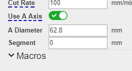
Anyone? In the setting below What does the A Diameter refer to? The workpiece or the roller?
If I assume it is the roller I enter a value of 35.3 (my actual roller diameter). The workpiece I am trying to cut is 51mm in diameter. I create a 160.14mm vertical line (equal to the circumference of the workpiece). And the resulting Gcode has the A axis move 519.85mm. It is not making sense to me.
+Peter van der Walt I am running GRBL 6 axis and GRBL-LPC. Both have a 4th axis output. My Y axis is independent of the rotary. Regardless this function works irrespective of the firmware or machine connected to Laserweb. I have just been trying to figure out the math that goes into the G-code generation.
+Peter van der Walt Okay, Degrees, maybe that is what I am missing.
However there is nowhere in Laserweb do I see this unit. The move A axis is specified in mm not degrees. How does one tell the machine to rotate 360° for example?
in my firmware do I set the number of steps the amount to do a full rotation or 1 degree?
If I want to create artwork that would wrap around my part completely how tall does it need to be?