Ah, that PSU. I was looking at the description for the one that @ttaago found (in the other post you linked to) that had 12V and 5V; and missed that you got the one with 24V, 12V, and 5V. Agreed you can run everything off that, except that again I would use the 5V reference on the LPS for the potentiometer and nothing else. I don’t think it really matters, but the LPS should be measuring relative to its own idea of 5V.
2 Likes
Still nervous about moving wiring around so I just continued labeling today.
Working off diagrams, trying to get wires labeled. Don’t worry, I am not going to run the ground in series. I did that before your message. I am going to move the new PSU ground to the ground but once I have 18AWG wire. That should be in the next couple days.
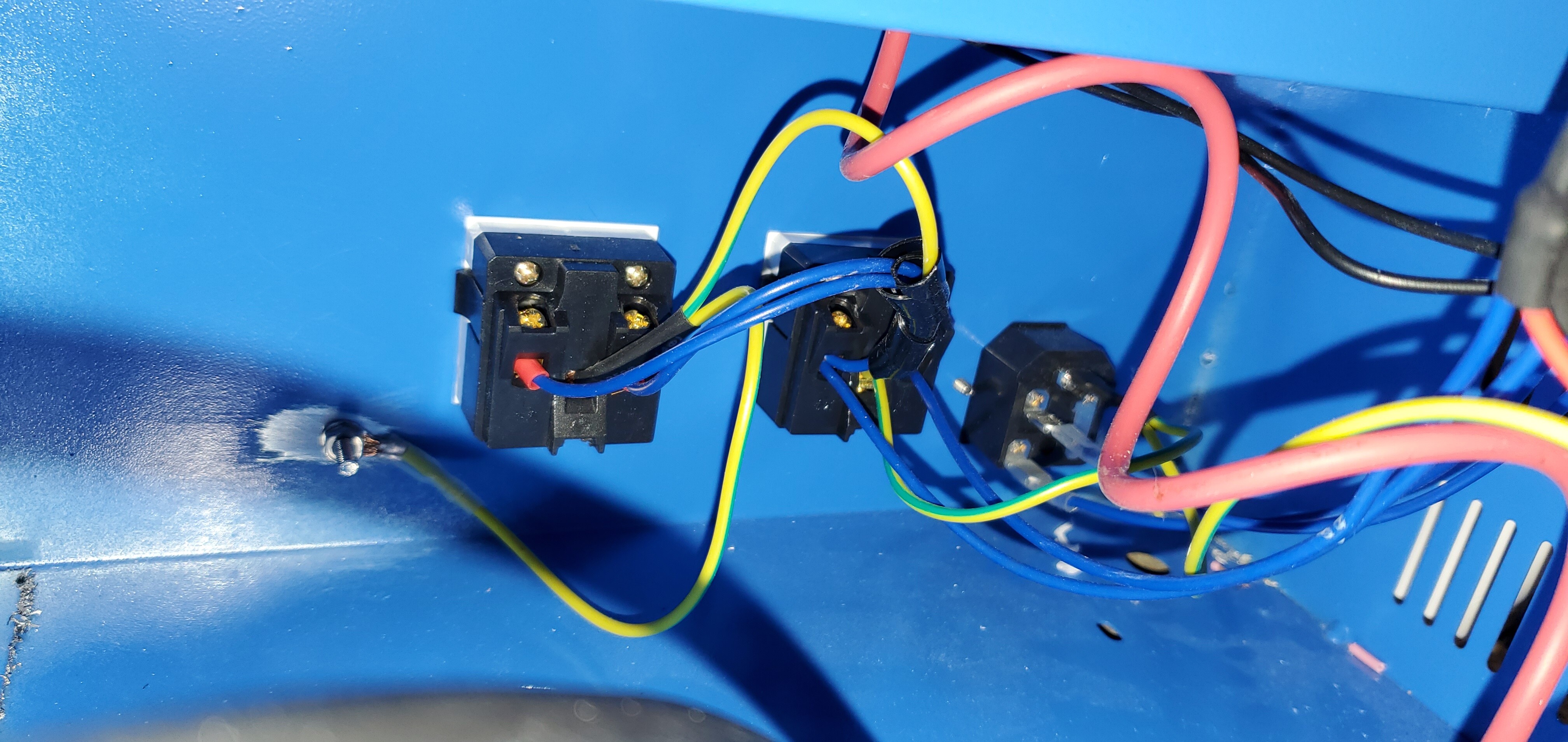
It looks like the AC input comes through the main and then to the outlets at the back. This is the bit that actually scares me. Want to ensure I don’t light up my K40 with flames or arcing instead of LEDs.
1 Like
It’s almost certainly OK. I don’t see how you would create a loop there. @donkjr would know better than me. I’m a programmer who dabbles with electrons; he’s an expert.
That’s right. Typical for accessory outlets. They, along with everything else in the K40, should be protected by a fuse in the main C14 plug that connects your K40 to the outlet. That fuse being 10A or less is why I said 18AWG — most C14 sockets aren’t rated for more than 10A anyway; many are rated for less.
3 Likes
My electronics work is limited to radios (basically modding them) for ham use. I only recently wired an outlet myself after my father in law couldn’t figure out the issue. I am enjoying this new stuff but an taking my time rather than rushing into the work before I truly understand it.
2 Likes
My advice:
Before rewiring-
Draw-up the wiring as it is. Include wire colors and endpoint designations.
You can use a schematic tool or just pencil and paper. I often use graph paper while I am wire tracing and then move that to a schematic capture tool at completion.
Most K40 owners skip this step but I have found it to be a good investment over the long haul. Especially when you make a mod and then forget what you did. In actuality, if you are tracing and marking the wiring the extra time to write it down isn’t significant.
Wiring
Then mark on that same drawing what you are going to change in some visible way.
Make the wiring changes one subsystem at a time and test before moving on to the next.
Editorial
If users that come to this forum had documented the wiring in their machine before and after mods most problems we encounter could be solved in 1/2 the time just by sharing the schematic.
Review
If and when you get these drawings done then I will be happy to review them before you start the wiring.
Examples
I often use Digikey schematic capture for simple stuff, stuff that does not need electrical or PCB modeling. This tool is crude and limited but free and simpler to learn than most EE tools. It’s also easy to embed diagrams in blog posts. It’s better to use a tool like Eagle but that takes more of an investment in time and $$. I am sure there are other open-source and free tools.
My original machine with simple mods: https://www.digikey.com/schemeit/project/k40-wiring-GCKOUK0100Q0
This is my modified machine (probably out of date); https://www.digikey.com/schemeit/project/k40-s-21-8SM4SO8200E0
4 Likes
Looking back at your post.
What are you trying to accomplish with the new triple output power supply?
@ttaago added a supply because his replacement LPS did not have enough 5V and no 24V to run the controller. Your situation is different?
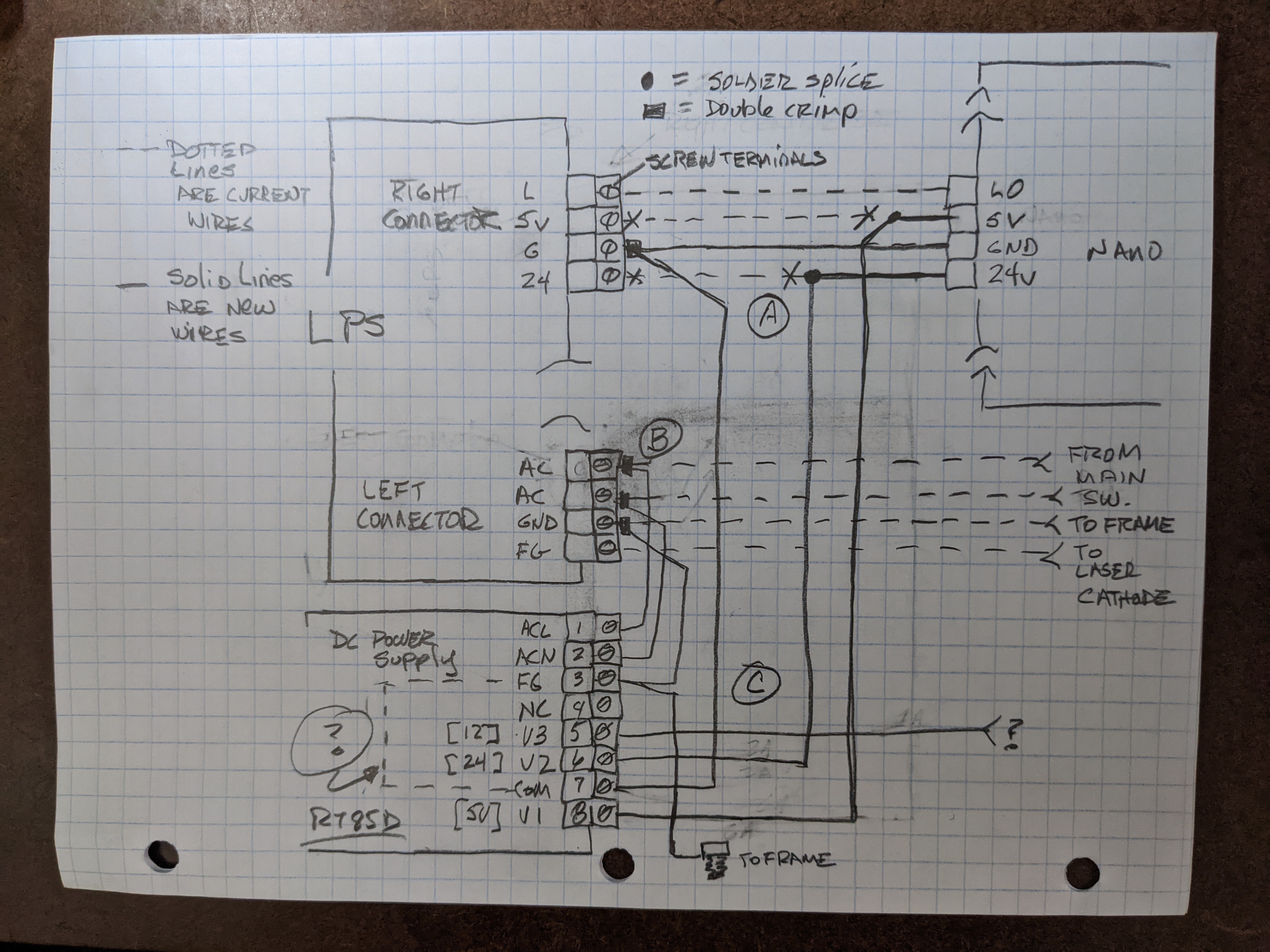
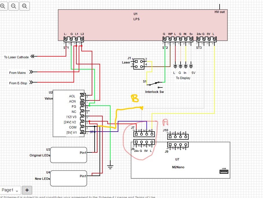
In any case here is a drawing to help you decide how to add the DC supply to power the nano.
I separated the wiring into Sections A, B, C.
The dotted lines represent what I think is current wiring
The solid lines represent wiring changes
The X on a wire represent were a wire is removed
I did this from what I could glean from the pictures of your machine and the PS specs.
Your machine may vary from this so adjust accordingly.
Please check everything carefully. Let me know if anything looks strange or wrong.
A
- The LPS-L to Nano-LO wire is left alone
- The LPS ends of the nano 5V & 24 wire is disconnected at the LPS and connected as shown to the new supply. If the wires are not long enough I would solder-splice/shrinkwrap longer wires onto them.
- The Gnd that goes between the LPS and Nano is left alone. A wire is added from the LPS-G screw terminal to the DC supplies Com connection.
B
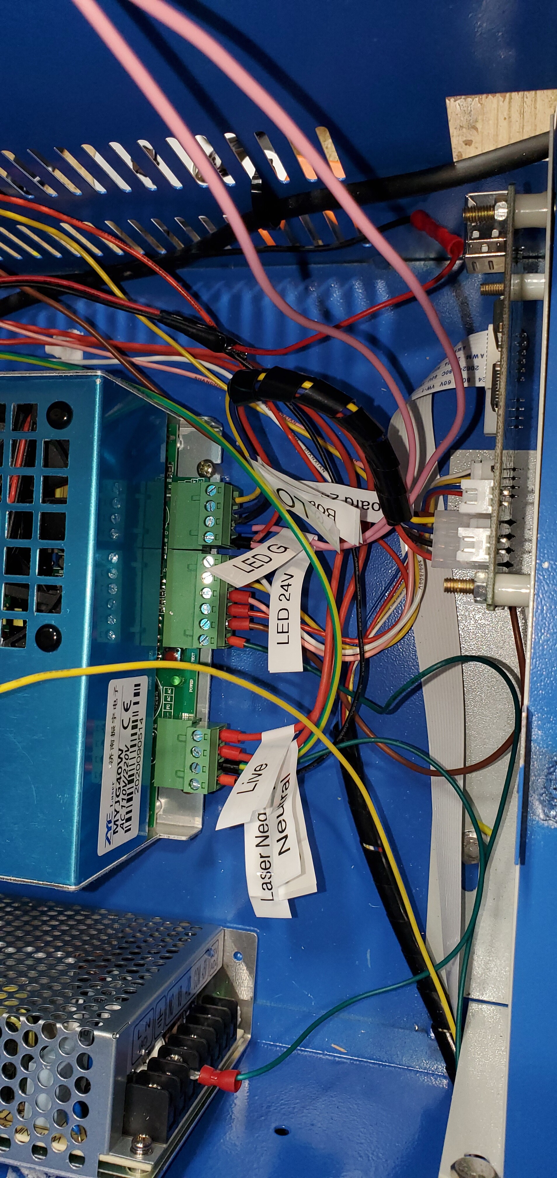
- The AC, AC, & Gnd wires from the LPS ac connector [left connector] are daisy chained over to the DC supplies AC connections as shown.
- Check to make sure that the GND on the LPS is connected to the frame.
C
- Connect the DCPS-FG to a screw in the frame. I would put a stud in the floor between your DC supply and the LPS so you have easy access from both.
- The 24v, 5V are already connected from previous wiring
- I do not know where you want the 12V connected
- Check with an ohm meter that the DC supplies FG and Com terminals are connected together internally
Wiring and testing:
- I would wire up B first and before connecting anything to the DC supply verify the output voltages are on the terminals you expect and the correct value.
EDIT: The DC supply specs refer to voltages as both V1-3 and also Channel 1-3. I assumed channels and V are the same so you should check on the actual supply. - Then wire A and C.
- With the DC power plug to the nano unplugged from the nano verify the correct voltages on the correct pins.
- At this point there should be nothing connected to:
- LPS-24V
- LPS-5V
- Then plug in the nano and power up and test everything
4 Likes
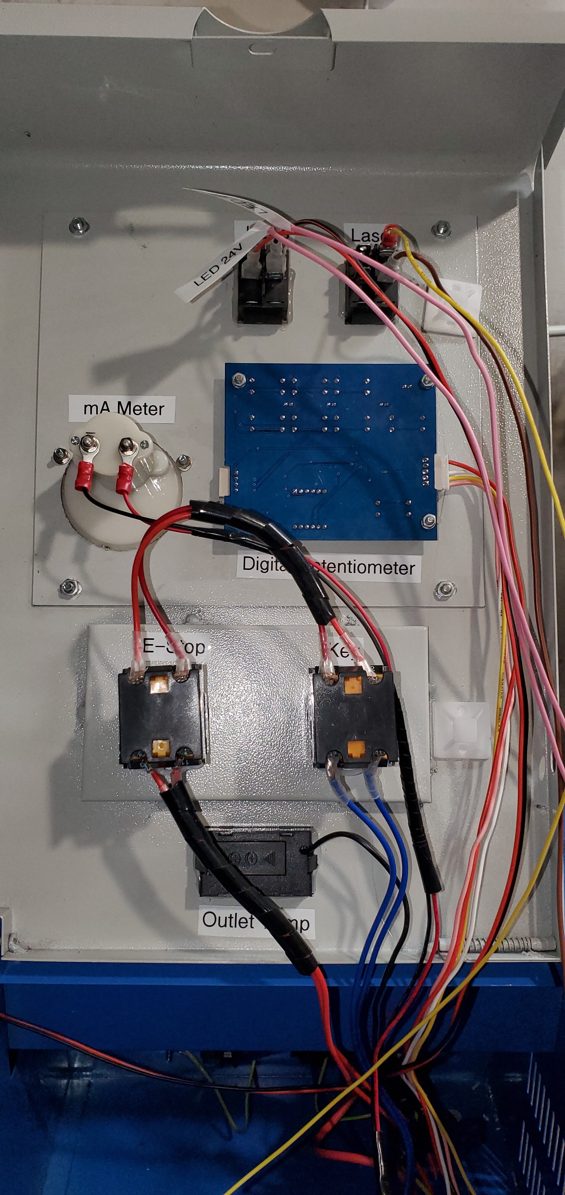
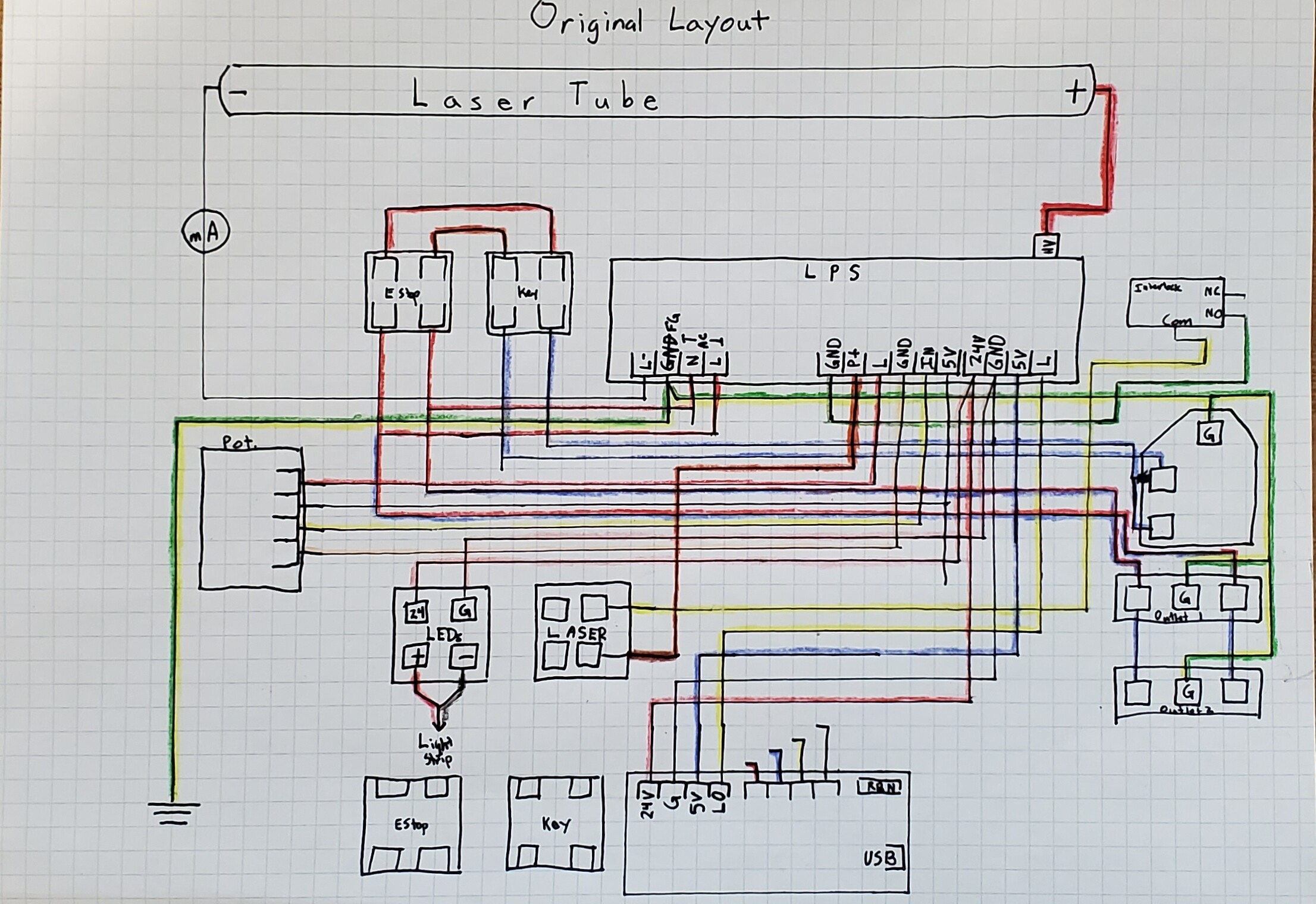
@donkjr Thank you for the incredible information and work that you provided for me. I truly appreciate it. I worked on my drawing of the unit as it arrived to me today. The only change that I have made is adding the mA meter.
As to what I am attempting to achieve: not a lot yet. I want to take some of the load off of the LPS and move it onto the new PSU. From my reading, this will help since LPS is at its limit with stock wiring. I want to be able to add lighting, gauges, whatever other electronics I need to, in the future.
I attempted to figure out Scheme-It but that is going to take me a bit to figure out. I drew (by hand) a schematic of the system. I apologize that the colors of the wires are so close. I have not changed wire colors at all since I received the machine. The wires from the bottom of the E-Stop are Red and run to AC N/L. But, they are also spliced into outlet 1 (right most outlet near Main) with Blue wires.
2 Likes
Looking good.
One way to make the drawing more legible is to make two drawings one that just shows AC and one that shows all non AC stuff.
What is the box on the left labeled Pot.?
1 Like
Good idea! That is the digital potentiometer (if that is what it is called). I am working in scheme-it now trying to get it figured out. I am not entirely sure how to make the main connector there (the C14/15).
1 Like
Share the schem-it drawing and I will help if you want.
Not sure what you mean by “digital” potentiometer? Picture?
Do you have a digital control panel?
Sorry for the delay. Not feeling great today. I wasn’t sure what the control panel is called. It is a digital control panel (not a digital potentiometer). I added the mA meter. I think that scheme-it at least looks right even if my choice of symbols is not perfect.
Ok I will take a look…
1 Like
Absolutely. That would be appreciated, in fact.
Well I have never shared a schematic with this tool before.
It seems that the person your sharing with cannot edit the original.
After editing a shared schematic you can save it in your own account but not back to the owners original :(((
So I have an edited version in my account. https://www.digikey.com/schemeit/project/k40-original-modified-31366790c8ad4d25bf7bb85e0dc10132 and you can see the changes I made. However I cannot give you the source in any way I have found.
I tried to cut and paste my version into another tab in yours and that will not work either. Grrrr.
There is an export but no import either ,uggh!
I guess you can share but not collaborate. This kind of missing function is why the tool has limited value.
It is however fine if you use it and share but without collaboration
Anyway you can see my changes you will just have to repeat them.
Thanks for working on that @donkjr! The ability to collaborate on a design would definitely be useful. I have access to the entire autodesk suite through my grad school for the next year. I really want to learn to use Fusion 360 and Eagle eventually.
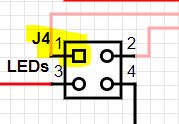
I see the changes that you made. They definitely improve the schematic. Are you asking about J4-1? I picked those symbols more because they had the right number of pins than for whatever their actual use should be. Later, I discovered the ability to use pins in the custom symbols area. I do have switches on my panel for both the laser and the LEDs.
I will attempt to turn the drawing that you did of the new layout into a schematic on scheme-it tomorrow. I will send you a link once I have completed it. I will attempt to incorporate what I learned from the redesign that you did.
1 Like
I have completed the new schematic. I haven’t left anything out, I hope. Here is the link to the schematic.
I bought another strip of LEDs to add. They will be powered by the PSU 12v. These are the ones that I bought.
Please let me know if you notice anything that I missed.
1 Like
@donkjr I used the above wiring to rewire. Every worked, except the stepper motors. Normally when I fully enable the laser, it goes to home. However, since the retiring, the laser head does not move. I disconnected the 24v and 5v wire and put them back to the original connectors. It worked. so, going to troubleshoot more…
I see two problems.
A: That connector is shown flipped horizontally. The L signal it on the right looking at the connector. The connections by name are connected correctly in the drawing so hopefully it just a drawing error not a wiring error.
B : I detect that the real problem is that there is no ground between the new DC supply and the nano?
My guess is that the led lights worked but not the nano.
When adding power to a system like this I always check the output with a DVM before I connect it to the load (nano). Make these checks referenced to all the grounds in the system.
In this case if you checked the DC supply relative to its ground it would have checked good.
Checking it relative to the nano’s ground would have read incorrect.
3 Likes
This fixed the issue. I got my new LEDs wired up as well. I cut the strip down and now have a short (5ish in) strip to put in the electronics compartment as well.
3 Likes