A Mathematical Valentine's Day gift: Intransitive Dice

A Love Story

My wife, a mathematician, asked whether I could machine some intransitive dice for her. She had in mind simple six-sided dice:

Consider the following set of dice.

  • Die A has sides 2, 2, 4, 4, 9, 9.
  • Die B has sides 1, 1, 6, 6, 8, 8.
  • Die C has sides 3, 3, 5, 5, 7, 7.

The probability that A rolls a higher number than B, the probability that B rolls higher than C, and the probability that C rolls higher than A are all 5/9, so this set of dice is intransitive. In fact, it has the even stronger property that, for each die in the set, there is another die that rolls a higher number than it more than half the time.

(Yes, this is kind of like “rock paper scissors”)

Note that the numbers on each die add up to 30, and that each number is repeated once.

I noticed, though, that there was another set for which each die has no repeated numbers, all the numbers are two-digit primes, and they still each add up to the same number. It’s a bit more of a challenge, though, because they are dodecahedra.

It is also possible to construct sets of intransitive dodecahedra such that there are no repeated numbers and all numbers are primes. Miwin’s intransitive prime-numbered dodecahedra win cyclically against each other in a ratio of 35:34.

Set 1: The numbers add up to 564.

PD 11 13 17 29 31 37 43 47 53 67 71 73 83
PD 12 13 19 23 29 41 43 47 59 61 67 79 83
PD 13 17 19 23 31 37 41 53 59 61 71 73 79

I decided that I had a Valentine’s Day project to start.

The only question was whether the dice were a valentine’s day gift from me for my wife, or the shop time was a valentine’s day gift from my wife to me! :thinking:

A Machining Problem

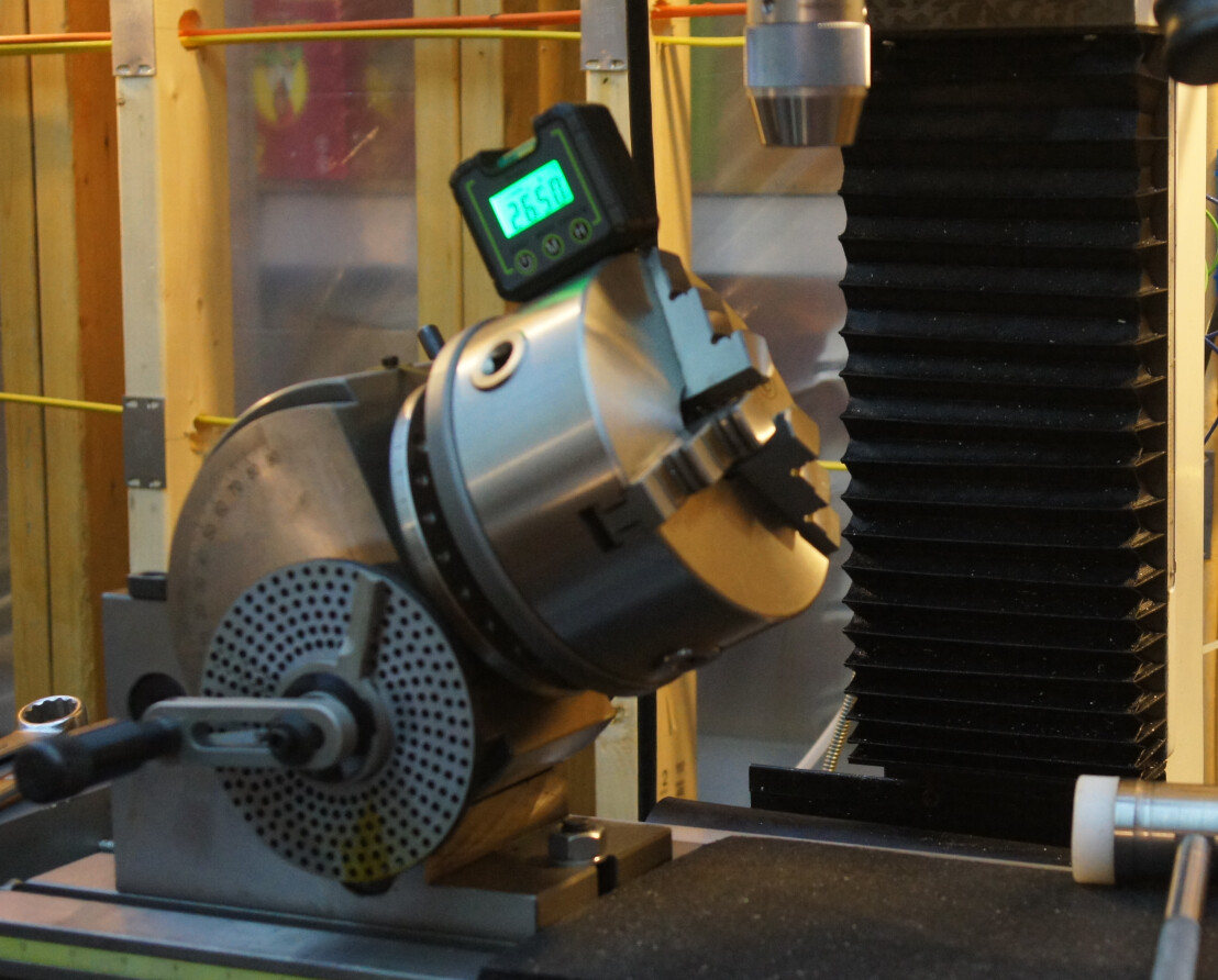
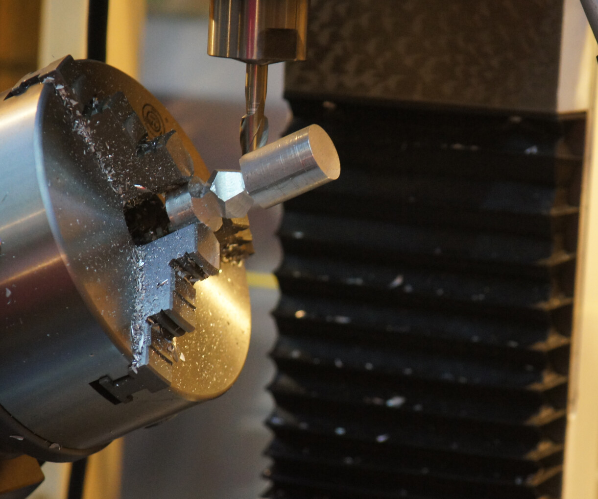
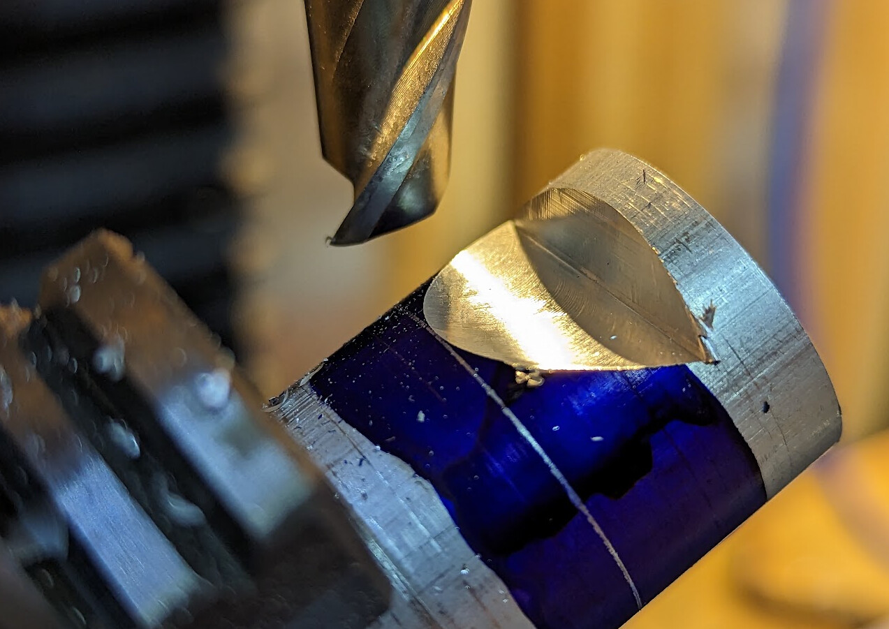
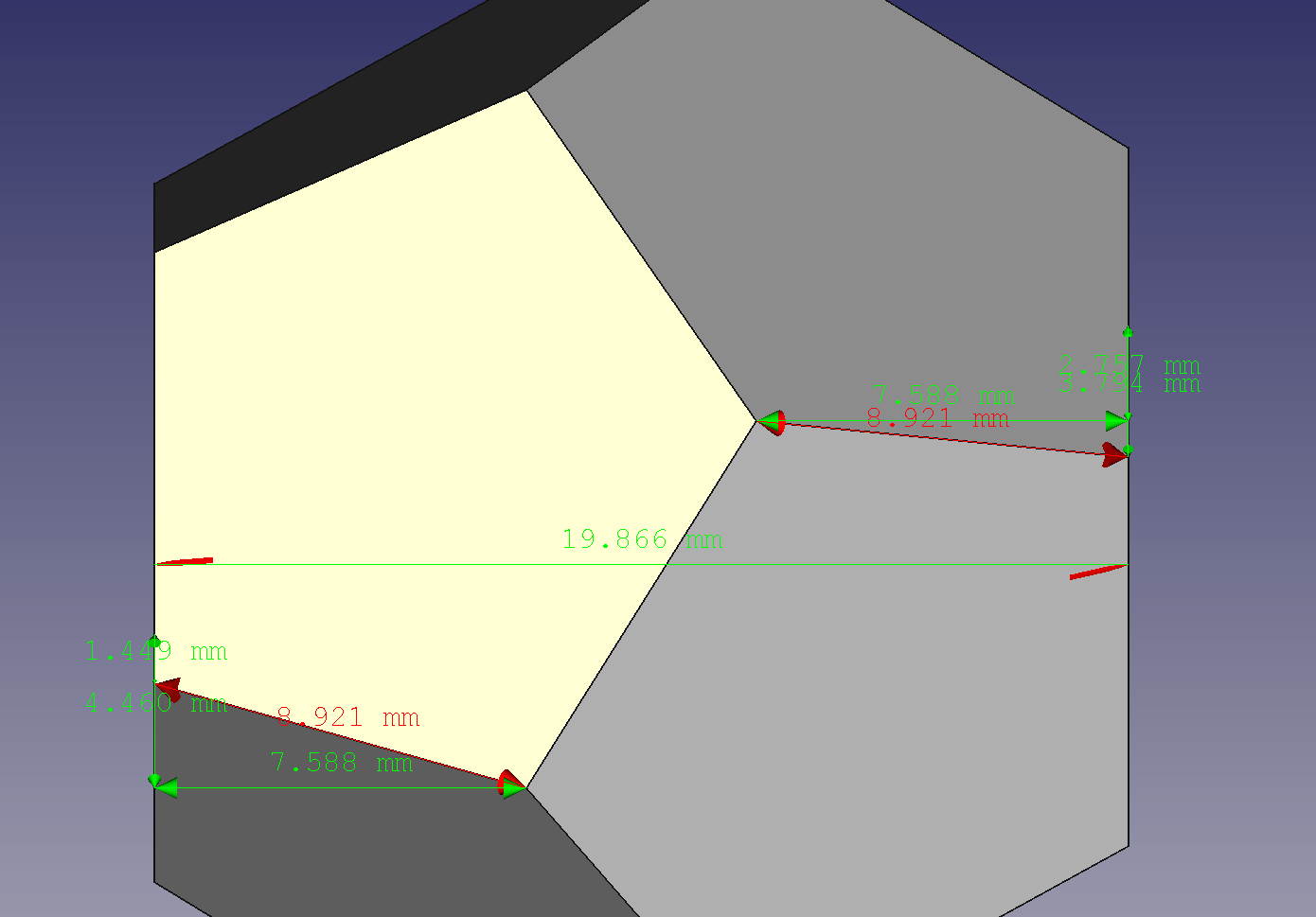
Dodecahedra do not have 90° angles anywhere. The angle between faces is about 116.5°, and machinists like 90° angles. I used the FreeCAD Pyramids and polyhedrons Workbench to work out angles and sizes and got to work.

  • Set the dividing head set at 26.5° (116.5° - 90°) and put 1" aluminum stock in it
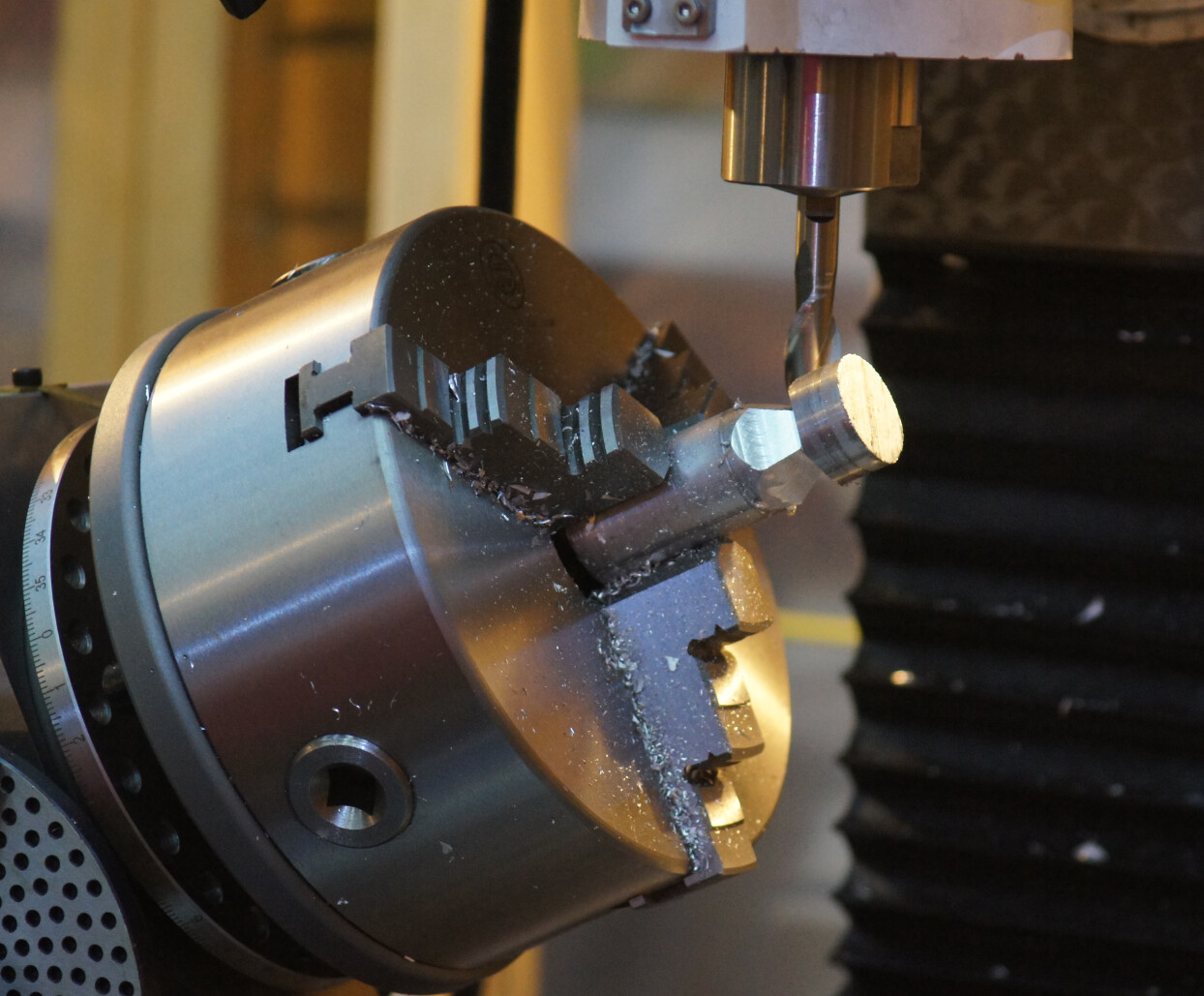
  • Cut every 72°, 15mm from the surface of the stock
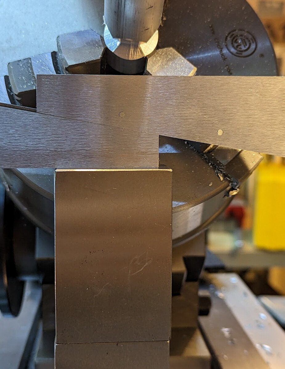
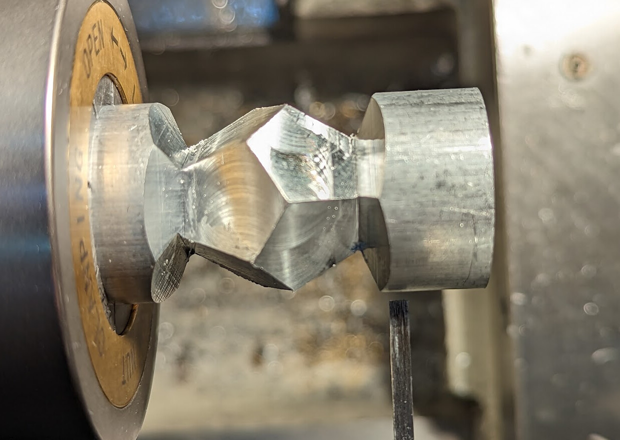
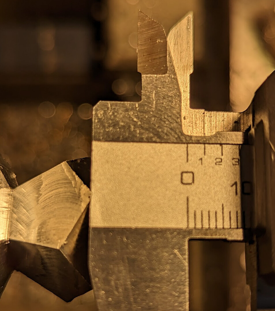
  • Reverse stock, use an adjustable parallel to line up a cut face parallel to the table, then cut down to 19.87mm between the new face and the opposite face aligned with the table and 14mm in from the vertex that is formed
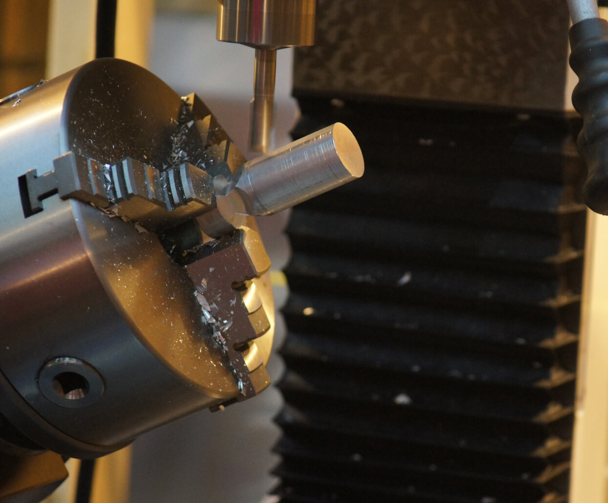
  • Again cut every 72° to measure across opposite faces
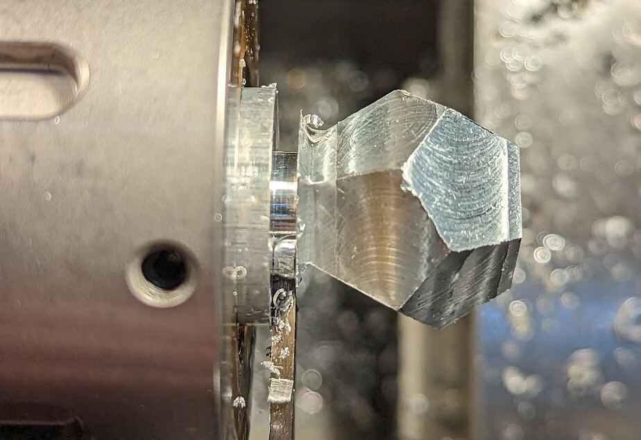
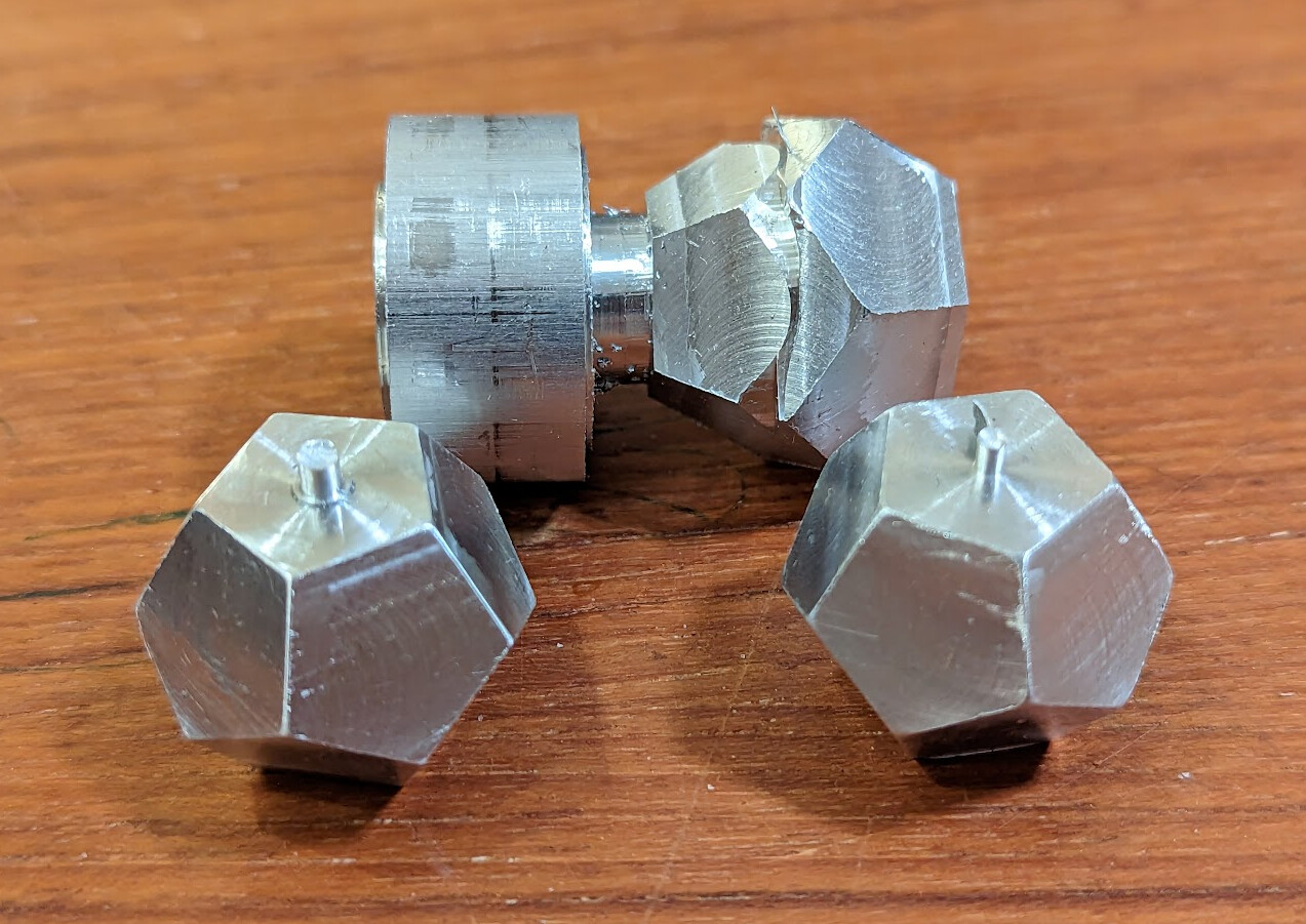
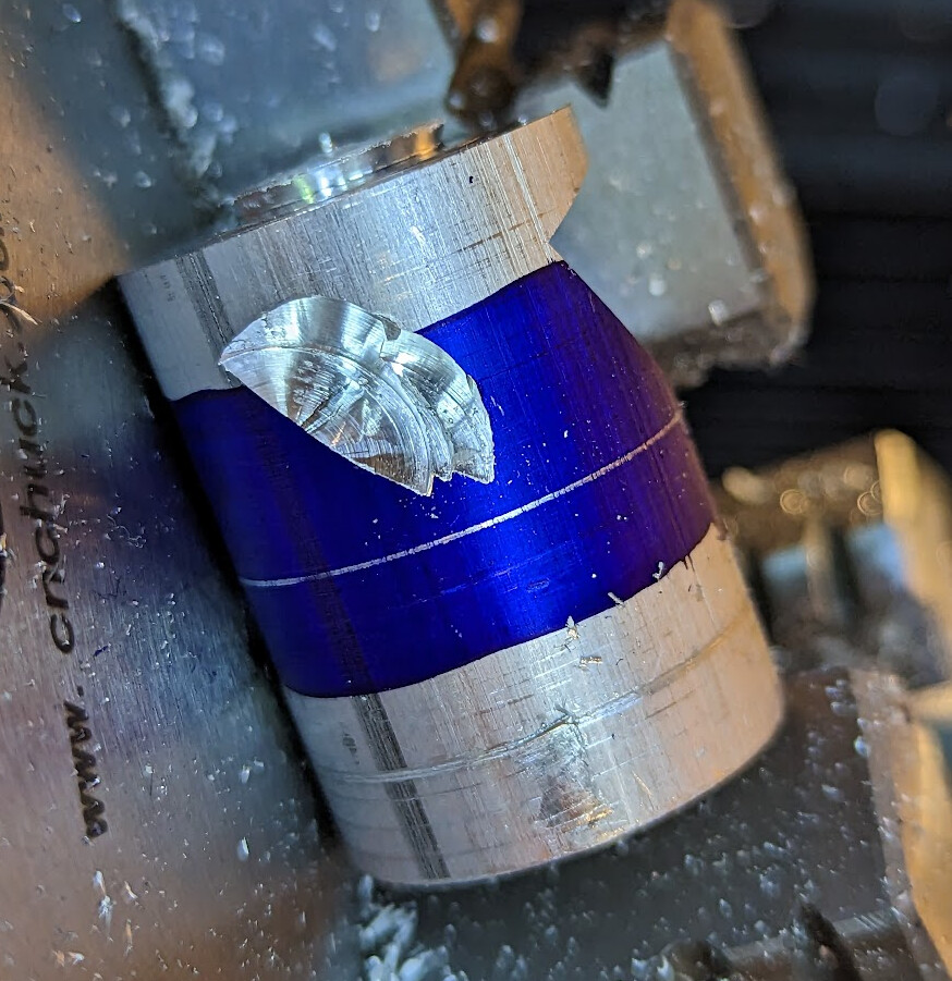
  • Transfer to lathe, face off one end 7.59mm from a near vertex, then part off to length 19.87mm
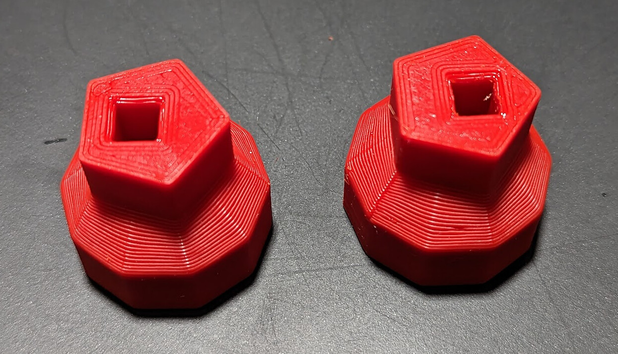
  • File off the parting nub, or print soft jaws to hold the dice in place to mill off the parting nub. I tried both, and settled on the soft jaws. Printed in PETG with all perimeters and 90% extrusion for high strength.

I discovered that I could make all three dice out of a single rod about 120mm long, as long as I didn’t make any mistakes. (I did make some mistakes, sadly.)

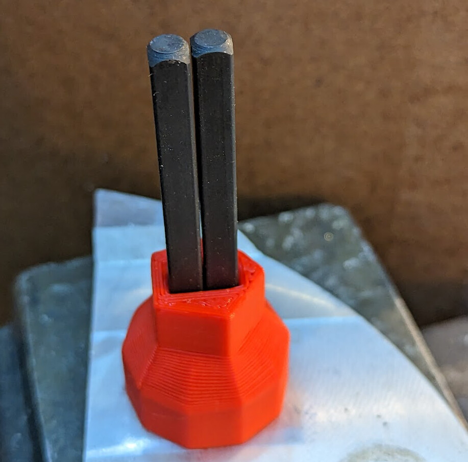
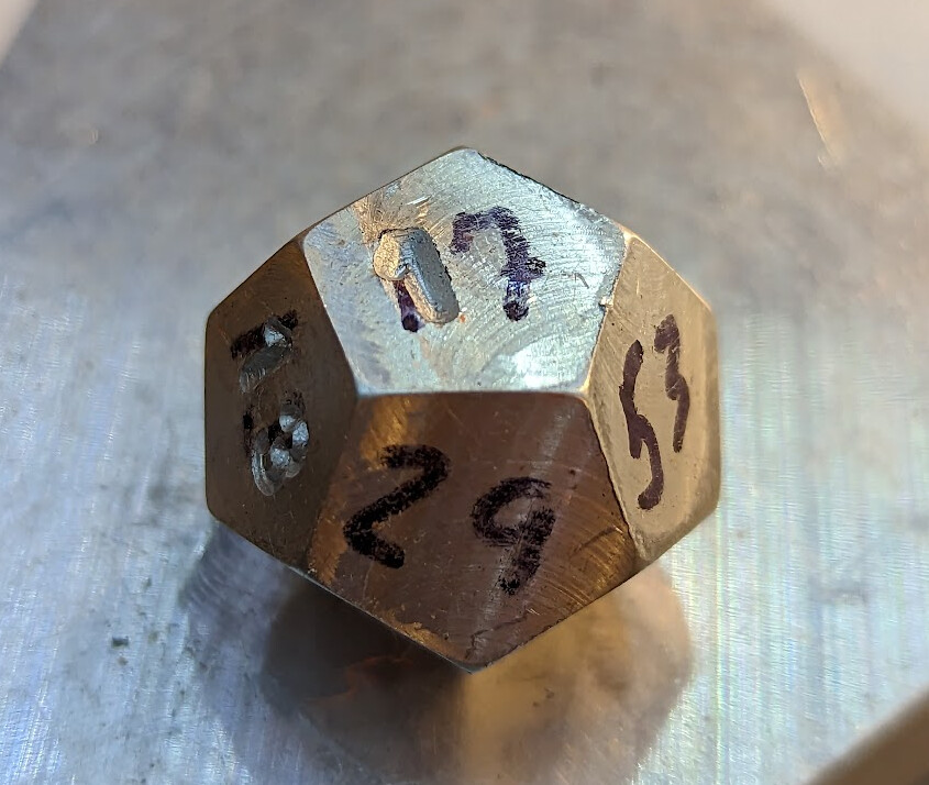
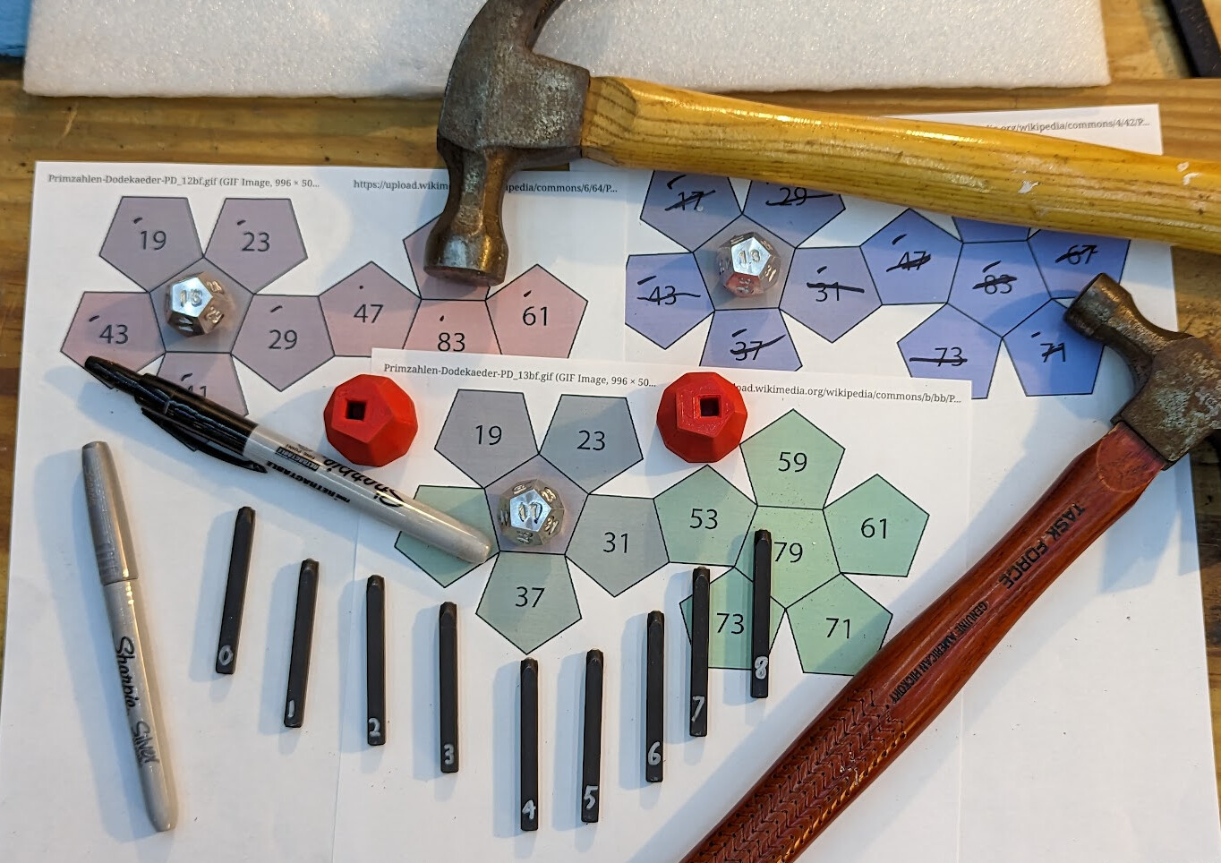
Then I 3D printed two alignment guides to hold punches, and punch the numbers into the faces. I designed these guides in FreeCAD, which actually made it pretty easy! :tada:

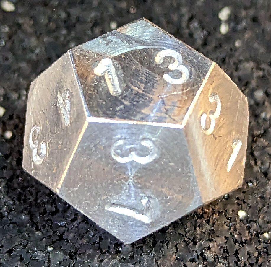
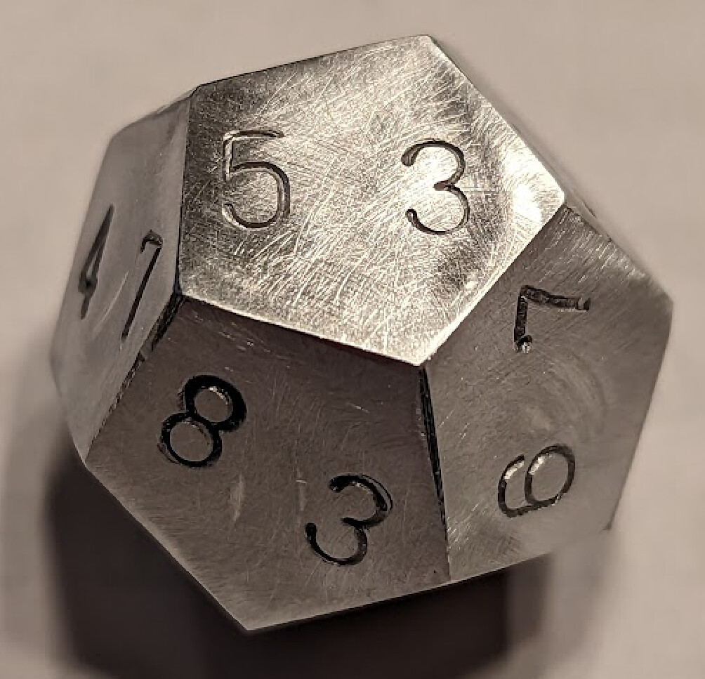
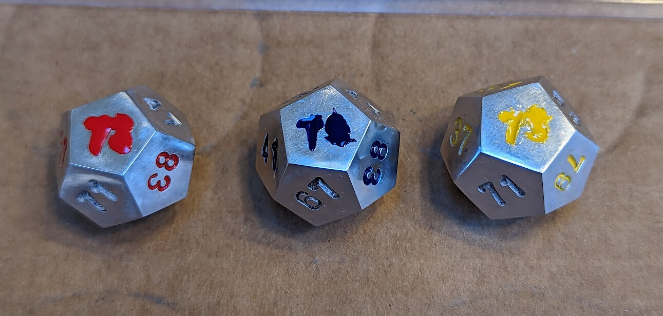
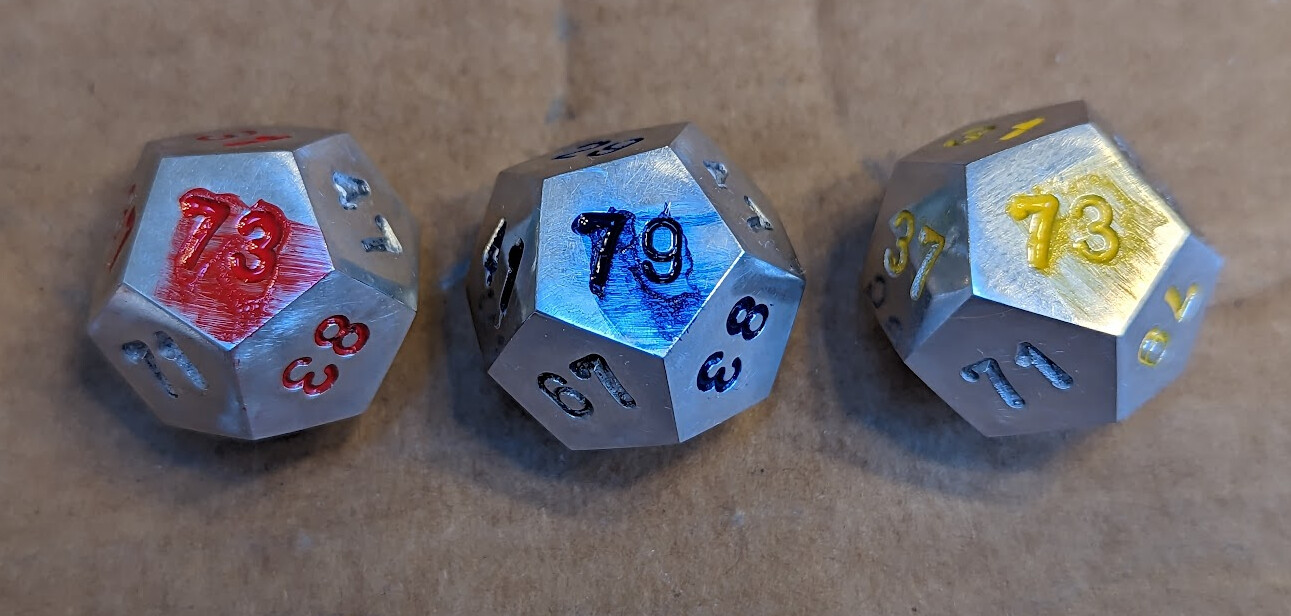
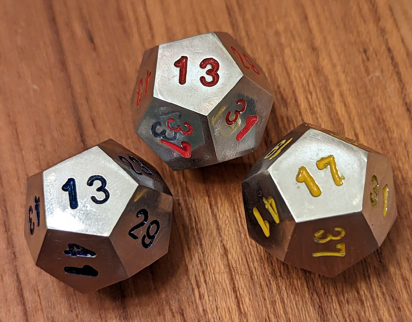
Of course, punching the numbers in distorted them a bit. I colored the faces with sharpie, wet-sanded them with oil down with 500 grit sandpaper on a flat block until the sharpie was gone, then cleaned them and did the same with 1200 grit, and finally polished them all over with Mother’s Mag and Aluminum polish, and cleaned them thoroughly.

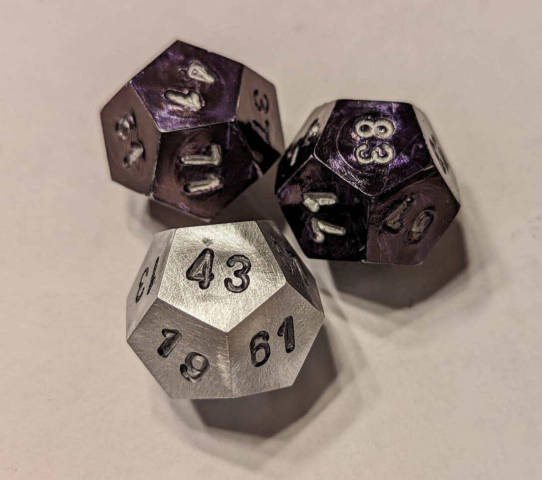
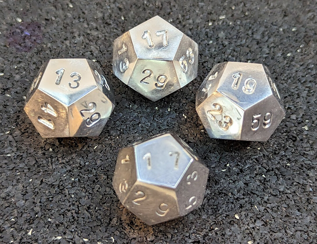
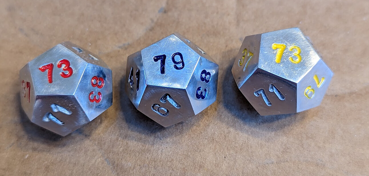
Then I used 1ml syringes to put tiny drops of Testor’s enamel into the stamped numbers, wiped off some of the excess, waited an hour or so, and then used paper towels and fingernails to clean the enamel off the polished surface, leaving the enamel in the stamped number. I used different color enamel for each die, so that you can tell the precedence between the dice: Blue beats Red, Yellow beats Blue, and Red beats Yellow.

By Valentine’s day, the enamel should be fully cured!

IntransitiveDice.FCStd (636.1 KB)
PunchGuides.obj (710.7 KB)
SoftJaws.obj (158.6 KB)

Build log with lots of pictures to follow!

4 Likes

Dividing Head Setup

I zeroed out my digital inclinometer on my mill bed (it’s about 0.25° out of level itself), and then set my dividing head to 26.5° (sorry for the blurry picture, there’s a reason I don’t do photography for a living…).

I put an offcut of 1" stock in it, with a mark you can’t see at about 30mm from the end. Yes, this is more than the 13.12mm that I need for the first face I will cut; I need about 15mm of remaining stock to hold firmly in the jaws later when I reverse it. (I tried with only about 5mm later and made a piece of scrap.)

Because my largest 2-flute endmill is ½" I had to cut the face in two steps. I set the X hard stops on my mill to cover the range of travel, I needed, and did my first, deep cut conventionally (here, this meant moving the table back, so that the relative motion of the end mill relative to the part was towards me), then stepped over about 3mm and did a climb cut through the last 3mm. The dividing head is stiff enough that the climb cut was just fine, and it sped up the operation a little bit.

I started at the 0° position which has a pawl to hold it in place, but all the other locations are multiples of 72° and need to use the friction lock. I marked those locations with a fine sharpie to help me move to them quickly, and used a visor loupe to accurately locate the index each time. I tightened the friction lock very tight to avoid creep. After five forward-and-back cuts, the stock looked like this:

Then I flipped the stock end for end, and used an adjustable parallel on top of a stack of 1-2-3 blocks to align one of the cut faces with the table.

With my right hand, I both tensioned the parallels and jiggled the stock while tightening the chuck with my left hand, to make sure that I got the stock properly aligned with the axis and the face at the bottom tram to the table, and cranked down hard on the chuck key. I did not want to lose this work!

I raised the quill, zeroed the quill DRO, and took an initial cut, measured across the bottom flat and the new top flat, and then lowered the quill by the difference from my 19.87 target. I put my micrometer in incremental mode from 19.87, which meant that it directly displayed the amount of additional quill travel which now read directly on the quill DRO. After I moved it, I re-zeroed the quill DRO and cut all five faces, the same as the first side, except that I made sure that I was 14mm from the new vertex rather than 15mm from the surface as my reference for cutting far enough. I had to move the hard stops to do this.

After this, I had 10 of the 12 faces cut.

Lathe Work

I started on the six-jaw because it was installed, but switched to the collect chuck for later dice. There was no flipping here; there really couldn’t be.

First I parted off the end to make a ~1cm disc that I can maybe use later for something else.

Then I faced it lightly with an aluminum-cutting insert to make sure that I had a flat end, used calipers to measure the distance to one of the near vertices, and then cut off the excess over 7.59mm. I did this by setting he calipers to 7.59mm, zeroing it, setting it to inches, and then using a dial indicator against the carriage to face off the remainder.

Next, I cut down the tangent faces against the remaining stock so that I could part off without the slant of the faces causing the parting blade to wander.

Initially, I tried to part off exactly to length, trying to do this as only machining, but after my initial experience, I cut it off about 0.1mm too long and set it up in custom soft jaws in the mill to face it off to length.

If I had done the parting off better, this mill work would not have been necessary. But I’m still learning…

1 Like

Impressive design and machine work!

1 Like

Numbering the Dice

Initially, I intended to punch both digits at the same time, using a single punch holder with both digits side by side.

(Trust me, there’s a die perfectly captured under that plastic, you just can’t see through it!)

However, I could have tested that combination on a piece of scrap before committing to a die that I’d put substantial time into! Those digits are just a bit too far apart.

Now I was committed to having made a test die, so I kept working on it. After a brief panic that I didn’t have a “9” punch (it’s… the “6” punch upside down) I got all the numbers whacked into the surface.

I sanded with 220 grit and then 1200 grit, then polished. This made it clear that 220 grit was too coarse; one more example of value of making a test article first.

So for the next set, I made two separate punch guides that pulled the numbers 2.4mm closer together.

Then I wrote all the numbers where I wanted them, and followed up by punching the digits. It turns out that punching them separately made it easier also to punch them deeper. This was very helpful in the end for making them easy to read.

I used a silver sharpie to write the numbers on the punches in the same orientation as each other to make it easy to check that the number wasn’t upside down (or… was, if I was turning “6” into “9”). The hole in the punch guide was intentionally a tight fit, so I used the light hammer to set the punch in the guide, and the big hammer to whack the punch hard at least ten times (with only a single glancing blow against a thumbnail across all 72 digits, thus at least 720 whacks). I kept printouts of the three dice from wikipedia and followed the same layout.

While I made several mistakes (I had to make 6 dice to get three final ones), I never got a digit wrong. :tada:

Whacking numbers into them made the faces not flat; that metal has to go somewhere. This time I polished first with 500 grit, then 1200, then polished.

I colored them all over with sharpie before the 500 grit and 1200 grit polishing stages to make sure it was flat

Here’s the difference between 1200 grit and polishing with Mother’s:

Here’s a comparison between the test die and the final versions:

Coloring

I can’t just color all the digits the same. Somehow, the dice need to be quickly distingushable from each other. I thought about trying to anodize them and dye the dice different colors, but after I looked up how to anodize at home, decided that I’d take a different approach.

I bought a set of Testor’s enamel (memories of childhood model making!) to color the dice each with a characteristic digit color.

I bought some blunt syringes as well as one set of sharps. I ended up using the sharps because the blunts didn’t have caps to keep the paint in them from drying out. I removed the needle to fill the 1ml syringe with about 0.1ml of enamel paint, then firmly installed the needle back on the syringe body.

I thought it would be easy to just fill each digit with paint and let it dry.

I was wrong. Surface tension was not my friend.

I couldn’t get the recessed digits full without also getting paint on the face. Eventually, after some experimentation, I came up with this approach:

Put a couple drops of paint in the numbers and drag it around inside the recessed number with the needle, to make sure that it touches all the surface of the recessed number

Use the side of the needle to wipe the paint flat across the surface, then let it dry for about an hour

Use paper towel and fingernails to remove all the enamel from the polished surface

Repeat with the next face.

This took a few days.

And now, I’m waiting 48-72 hours for the enamel to fully cure.

Fitness for Purpose

These particular dice will not be pedagogically useful, because any pair of dice is almost balanced. “Miwin’s intransitive prime-numbered dodecahedra win cyclically against each other in a ratio of 35:34” so it will take a lot of throws before you are likely to notice a pattern.

These are just a labor of love.

Because the totals for the faces on the dice are all the same, these dice have the interesting property that if you throw them and record both the numbers thrown and who won, over time the total of the numbers thrown for each player across all the throws will tend towards being the same, but over time one player will tend to win more throws. It’s a little bit mind-bending!

So later, I will also make the simple six-sided dice that win with probability 5/9. Those have the same property, but it can be seen without throwing 100 or 200 times… :relaxed:

But those will have pips instead of numbers, and the pips will be machined, so I have to make my mill depth stop first so that the pips are all the same depth, and a vice stop so that I can reasonably quickly mill all the pips that are in the same relative position. I’ll still use some of the lessons I learned here, like drawing what I want on the face with a sharpie first so that I can keep track of what I’m doing, and I think coloring with enamel.

Also, I might try 3D printing dice in different colors, and machining them to final dimensions for precision and fairness (well, precise unfairness with these dice!)

Outtakes

Of these three dice cut together from one piece of stock:

One was half a millimeter too large to fit my 3D-printed fixtures because I somehow set the depth wrong when cutting the second set of faces and also had the height set wrong on the parting tool, leading to an unusually large parting nub. For another, I didn’t secure the power feed lever on the lathe, and it started crossfeeding at an inopportune time:

I thought I could get away with having only 5mm of stock left to hold for the second set of 5 faces:

I was wrong:

I’m sure I could have made it work with lots of light passes, but I’m not that patient.

/fin

Unbelievable work! You definitely have mad skills as a machinist and designer.
Just curious, if the edges of the dice are not the same, will that change the mathematical probabilities of the outcome.

1 Like

I did not try to crown the edges or vertices; it seemed that any effort to do so would make them less consistent (hard to describe this intransitive setup as “fair” with a straight face) because I couldn’t find a way to crown them consistently. So they have sharp edges and vertices, even more so after polishing.

The mathematical probabilities are based on the fact of the different numbers used on the sides, and are true only inasmuch as the dice are otherwise fair (equally likely to land on any particular face). It’s possible that I was inaccurate enough in machining that they are not perfectly equally likely to land on each face. But I’m not going to set up a robot and a machine vision system to roll each die 12,000 times and see how close to 1,000 instances each face turns up. :grin:

You can see this by taking any pair and enumerating all possible outcomes, and counting the wins between them. Assuming that each face is equally likely, this simple enumeration will tell you the probability of a win.

That’s particularly easy to do on the six-sided dice because each die has only three numbers, which are repeated with the same number on opposite faces for each die. So compare dice A and B from the set at the top. Each distinct outcome is equally likely:

2, 1: A
2, 6: B
2, 8: B
4, 1: A
4, 6: B
4, 8: B
9, 1: A
9, 6: A
9, 8: A

Out of the nine possible outcomes, A wins 5 times and B wins 4 times, so A wins 5/9 of the time (probability) or with a ratio of 5:4 (odds).

Similarly, B vs. C:

1, 3: C
1, 5: C
1, 7: C
6, 3: B
6, 5: B
6, 7: C
8, 3: B
8, 5: B
8, 7: B

Here you can see that B wins against C 5 times vs 4.

What about C vs A, though?

3, 2: C
3, 4: A
3, 9: A
5, 2: C
5, 4: C
5, 9: A
7, 2: C
7, 4: C
7, 9: A

C beats A 5 times vs. 4.

Like rock-paper-scissors, any die can be a winning die.

So if anyone challenges you to a game with these dice in the real world, tell them you’ll play if they choose the first die and you have the free choice of the second die, and make your bet proportional to the number of throws you make as well as your appetite for risk. :grin:

1 Like

What a super post. You really rolled through a lot of learning on this project.

2 Likes

I could have finished the final face using a superglue arbor instead of a custom 3D printed soft jaw. Here’s a really nice approach!

2 Likes

“My compliments to the chef.” as they say. What a fantastic project. Beautiful description also.

2 Likes

And now another video from Chronova machining all the platonic solids, and showing 4D variants:

2 Likes