Hi there, new user here- how’s it going? I have a question for anyone that’s familiar with the 3018 style machines (mine’s a Sainsmart 3018 Pro). I bought one of those cheap Z probes for it (with the pad and the crocodile clips) but it came just with bare wires and no means to attach it to my board. I assumed that it needed DuPont connections so I bought some female connectors and after attaching them I realised that it was quite a loose fit on the board so I resorted to sawing about 5mm off the connector so that it would fit snugly onto the pins. That worked for a while until the connection failed and I ended up gouging my probe with a V bit whilst trying to zero my Z-axis. I presume that the board needs a different standard of pin connector (one designed for shorter pins), does anyone know what I should be using instead? Basic electronics question, I know!
Attach pictures of your connector?
In that photo its pretty hard to see the connector.
If I had to guess its a dual row .1" pitch pin array??
Can you tell us the pitch of the pins?
How tall are the pins?
Do they look like these:
If so there are lots of choices on amazon but I dont know why the duponts you have would not work.
Here is a kit:
You will need a crimper unless you try and solder the pin-wire
Or these:
Hi Don, thanks for the reply. The pins are approximately a 1/4" tall; they do look like the ones in the link but it’s hard to get a sense of proportion from the picture alone. It might be the case that I did such a bad job of attaching the dupont connector that it didn’t provide a snug fit. I’ll have a look to see if the connectors I have will fit on their own without any wires attached.
I used this set of connectors, just for reference:
DuPont Connectors
I forgot to mention the pitch, I would say the pins are about a 1/10 of an inch apart.
Here’s some more pics taken with my crappy camera, if they are at all helpful:

After playing around with some unwired connectors I think I might be able to get the DuPont ends to work after all. I think I just need to push the inserts further into the socket. I thought I got them to click into place the first time, but obviously I didn’t push them far enough.
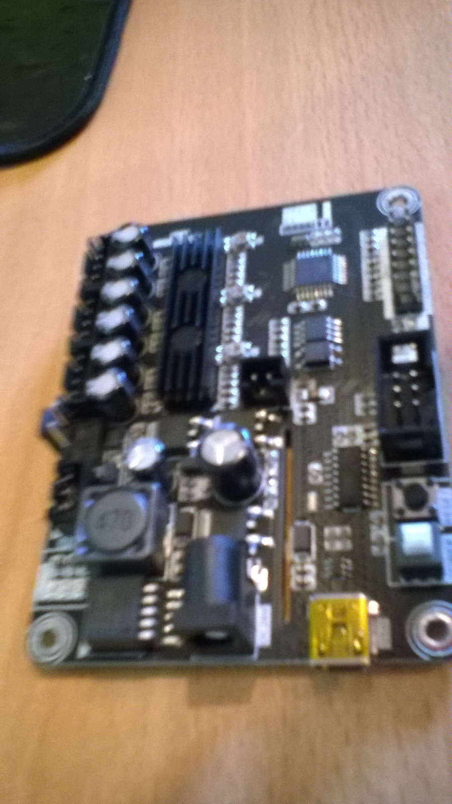
OK, found the board, I think:
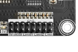
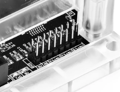
Those look like normal .1" / 2.54mm pin headers, so female dupont connectors would be right. Yes, if you aren’t used to making them, it’s easy to think that the crimp connectors are fully seated when they aren’t actually. If the connectors come out of the plastic blocks, then they definitely weren’t seated right. If the connectors get bent, or you have wire with insulation that is too thick, it can be difficult or impossible to get the connectors to seat properly.
Yup been there done that!
The pin should “click” when it goes into the housing correctly if not it will push out when inserted and create all kinds of intermittents…
Okay, thanks for the info! I’ve ordered a crimping tool which I think should help. Before I was using pliers to bend the tabs round, not ideal!
Funny thing about that is that I thought I had clicked the pins into place. It was only when I tried with an unwired plug that I realised how far they are supposed to go. Think I’m gonna have to shave a bit off the wire insulation so that they fit into the connectors easily.
If they are hard to insert, one trick is to use a small jeweler’s screwdriver to push on the crimp around the insulation.
The crimp tools can be tricky to operate correctly. I find that bending the outer crimps (the ones meant to bite the insulation) to slightly tighten them on the insulation before crimping makes it easier to hold everything in place while forming the crimp with the tool.
There are many youtube videos showing the crimping process. Here’s one that I found helpful:

Note that many of the comments in that video also referencing tightening on the insulation before crimping to make it easier.
Thanks for the suggestions. The problem I was having was not being able to fit the wire (with pin attached) into the housing as the opening was too small. I solved this by simply soldering some thinner wire to the ends and then adding the pins plus housing. I’ve just about got the hang of the crimping tool, I found that the outer crimps wouldn’t quite sit in the grooves of the tool so I’d squish them slightly in the very end of the jaws then sit them in the groove and apply the wire. The video you linked certainly goes into a lot more detail then the ones I watched and confirms to me that I’ve used slightly too much exposed copper in my crimps- explaining why it’s a bit difficult to slide the connector onto the PCB. Not perfect but it works!